Operating basics
R&S
®
RTA4000
35User Manual 1335.7898.02 ─ 08
4 Operating basics
4.1 Display overview
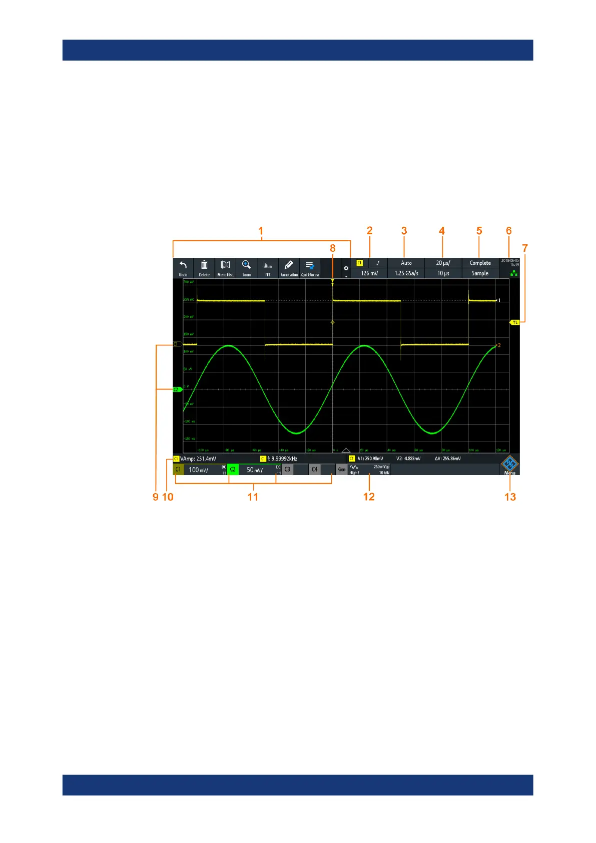
The touchscreen display of the instrument shows the waveforms and measurement
results, and also information and everything that you need to control the instrument.
Figure 4-1: Display of the R&S
RTA4000 with 4 channels
1 = Toolbar
2 = Trigger source, main trigger parameter (here: slope for edge trigger), trigger level
3 = Trigger mode and sample rate
4 = Horizontal scale (time scale) and horizontal position
5 = Acquisition status and acquisition mode
6 = Date, time, education mode if active (here: off), LAN connection status (green = connected, grey = not
connected, yellow = connecting)
7 = Trigger level marker, has the color of the trigger source
8 = Trigger position marker, has the color of the trigger source
9 = Channel markers indicate the ground levels; channel C2S is selected, i.e. it has the focus
10 = Measurement results (here: automatic measurements on the left, cursor measurements on the right)
11 = Vertical settings of active analog channels: vertical scale, bandwidth limitation (no indicator = full band-
width, B
W
= limited frequency), coupling (AC, DC, ground), probe attenuation. Channel 2 is selected.
12 = Waveform generator settings (requires option R&S RTA-B6)
13 = Menu button
Display overview
 Loading...


