163
Effects List
Overview Sound 1 Sound 2 Sound 3 Pad Sampler
Menu/System
AppendixSequencer
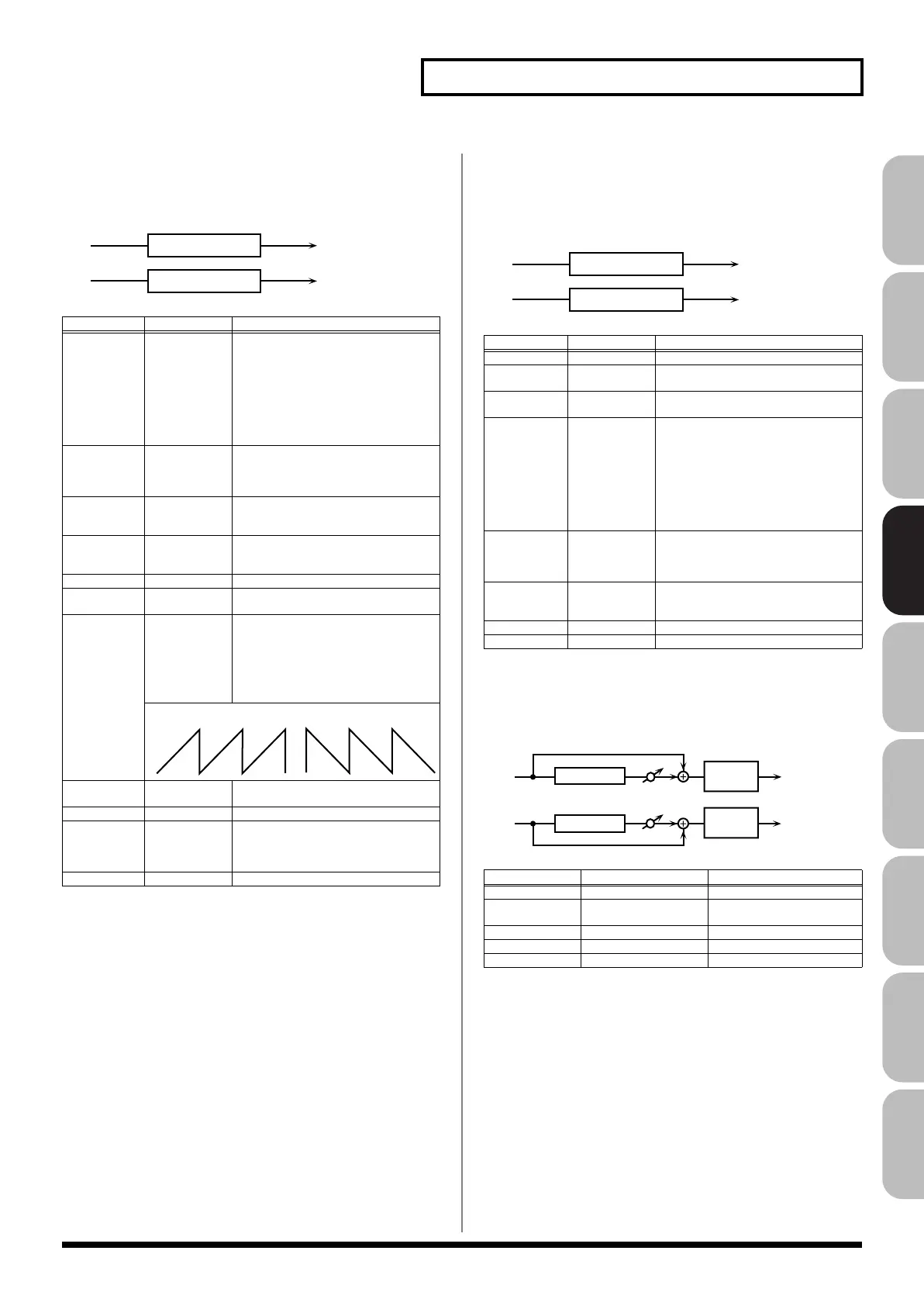
05: SUPER FILTER
This is a filter with an extremely sharp slope. The cutoff frequency
can be varied cyclically.
fig.MFX-05
06: STEP FILTER
This is a filter whose cutoff frequency can be modulated in steps.
You can specify the pattern by which the cutoff frequency will
change.
fig.MFX-06
07: ENHANCER
Controls the overtone structure of the high frequencies, adding
sparkle and tightness to the sound.
fig.MFX-07
Parameter
Value Description
Filter Type
LPF, BPF,
HPF, NOTCH
Filter type
Frequency range that will pass
through each filter
LPF
: frequencies below the cutoff
BPF:
frequencies in the region of the
cutoff
HPF:
frequencies above the cutoff
NOTCH:
frequencies other than the
region of the cutoff
Filter Slope -12, -24, -36 dB Amount of attenuation per octave
-36 dB:
extremely steep
-24 dB:
steep
-12 dB:
gentle
Filter
Cutoff #
0–127 Cutoff frequency of the filter
Increasing this value will raise the
cutoff frequency.
Filter
Resonance #
0–127 Filter resonance level
Increasing this value will emphasize
the region near the cutoff frequency.
Filter Gain 0– +12 dB Amount of boost for the filter output
Modulation
Sw
OFF,ON On/off switch for cyclic change
Modulation
Wave
TRI, SQR,
SIN, SAW1,
SAW2
How the cutoff frequency will be mod-
ulated
TRI:
triangle wave
SQR:
square wave
SIN:
sine wave
SAW1:
sawtooth wave (upward)
SAW2:
sawtooth wave (downward)
Rate # 0.05–10.00 Hz,
note
Rate of modulation
Depth 0–127 Depth of modulation
Attack # 0–127 Speed at which the cutoff frequency
will change
This is effective if Modulation Wave
is SQR, SAW1, or SAW2.
Level 0–127 Output level
L in
R in
L out
R out
Super Filter
Super Filter
SAW1 SAW2
Parameter
Value Description
Step 01–16
0–127 Cutoff frequency at each step
Rate # 0.05–10.00 Hz,
note
Rate of modulation
Attack # 0–127 Speed at which the cutoff frequency
changes between steps
Filter Type LPF, BPF,
HPF, NOTCH
Filter type
Frequency range that will pass
through each filter
LPF:
frequencies below the cutoff
BPF:
frequencies in the region of the
cutoff
HPF:
frequencies above the cutoff
NOTCH:
frequencies other than the
region of the cutoff
Filter Slope -12, -24, -36 dB Amount of attenuation per octave
-12 dB:
gentle
-24 dB:
steep
-36 dB:
extremely steep
Filter
Resonance #
0–127 Filter resonance level
Increasing this value will emphasize
the region near the cutoff frequency.
Filter Gain 0– +12 dB Amount of boost for the filter output
Level 0–127 Output level
Parameter
Value Description
Sens #
0–127 Sensitivity of the enhancer
Mix # 0–127 Level of the overtones gen-
erated by the enhancer
Low Gain -15– +15 dB Gain of the low range
High Gain -15– +15 dB Gain of the high range
Level 0–127 Output Level
L in
R in
L out
R out
Step Filter
Step Filter
L in
R in
L out
R out
Mix
Mix
Enhancer
Enhancer
2-Band
EQ
2-Band
EQ
Fantom-G_r_e.book 163 ページ 2009年7月2日 木曜日 午後2時55分
 Loading...