27
Jul. 2015 JD-XA
8. LED
This verifies the illumination of the LEDs.
+————————————————+
| 1.LFO_TRI |
| 1/84 |
+————————————————+
1. Verify that the LED displayed on the screen lights up
2. Press Enter.
The LED goes dark and the next LED lights up.
3. In the same way, carry out steps 1 and 2 for all LEDs.
* The segments of the 7-segment LED display light up in sequence, one segment at
a time.
4. When the last segment for the 7-segment LED display lights up, press
Enter again.
Execution advances to the next test item.
9. LCD
This verifies the display of the screen.
+————————————————+
|Press [ENTER] |
|LCD Check |
+————————————————+
1. Press Enter.
All dots light up.
2. Press Enter.
All dots go dark.
3. Press Enter.
A screen like the one shown below is displayed.
+————————————————+
|Press [ENTER] |
|Contrast Check |
+————————————————+
4. Press Enter.
Contrast is maximized.
5. Press Enter.
Contrast is minimized.
6. Press Enter.
A screen like the one shown below is displayed.
+————————————————+
|Press [>] |
| |
+————————————————+
7. Press to advance to the next test item.
10. A/D
This verifies the operations of volumes, pitch bend/modulation lever,
modulation wheels, pedals and the keyboard aftertouch.
+————————————————+
|WHEEL1 :---|
| 1/54 |
+————————————————+
* At the same time when this test item is enabled, the midpoint calibration of the
pitch bender and the minimum value calibration of the modulation lever start.
Do not touch the pitch bend/modulation lever.
Enabling this test item while the pitch bend/modulation lever is at an angle
causes the messages BEND ADJ ERR! or MOD ADJ ERR! to appear. In this
case, re-enter the test item while the pitch bend/modulation lever is not touched.
1. Connect a foot switch to the HOLD jack.
2. Connect the expression pedals to the CTRL 1 and 2 jacks.
3. Operate each component which LED lights up from minimum to
maximum, and verify that the value displayed on the screen changes
from 0 to 127.
At the aftertouch test, slowly press the center C key, and verify that the
displayed value changes from 0 to 127.
For the volume without center click, check the minimum value (0) and
maximum value (127). For the volume with center click, check the
minimum value (0) and maximum value (127), and then check the center
value (64).
At last, the Portamento Time volume test ends, Remove Pedals. is
displayed.
4. Detach the foot switch and the expression pedal.
Execution automatically advances to the next test item.
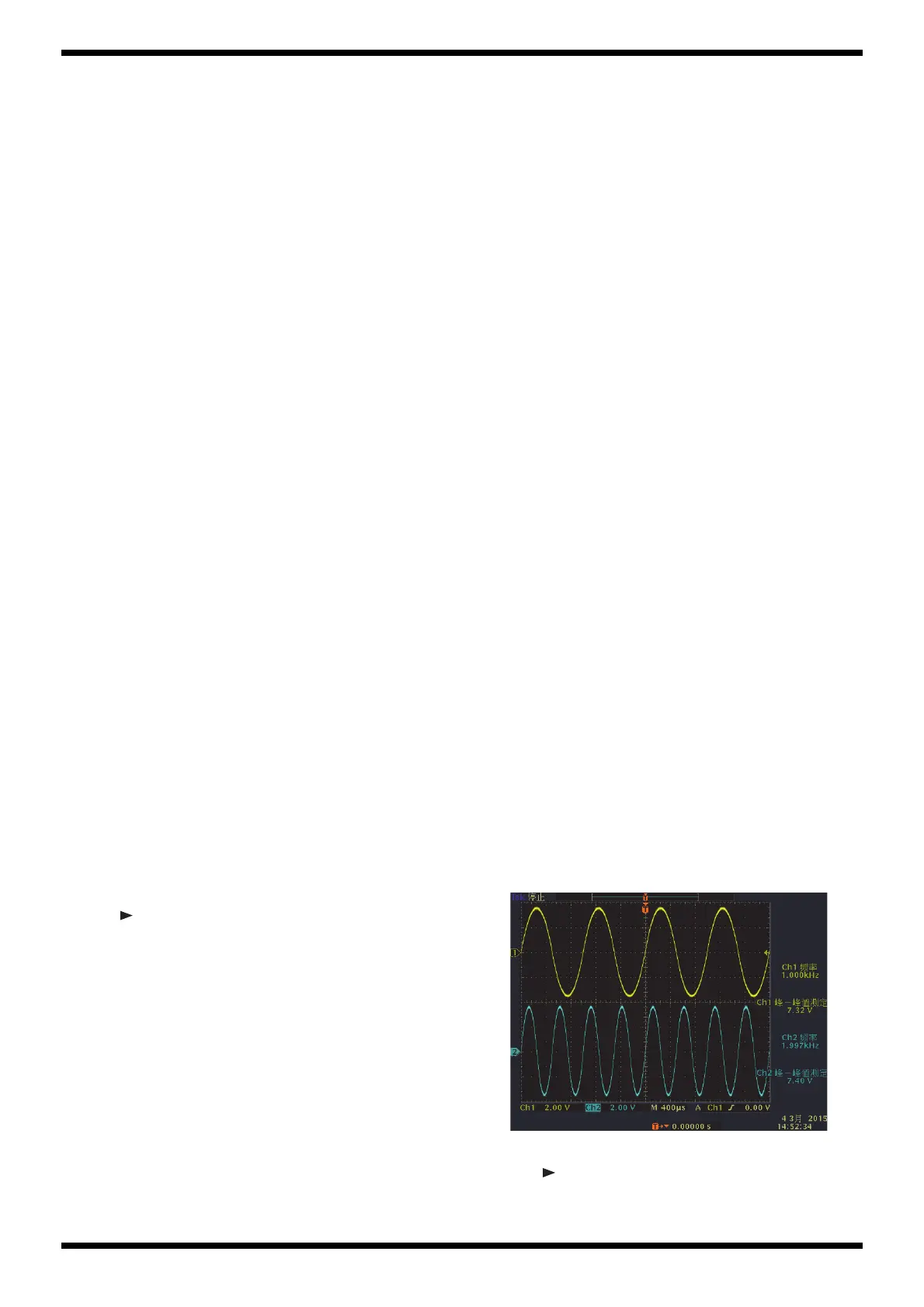
11. Phones Out
This verifies the operation of the PHONES jack.
+————————————————+
|Phones Out :SINE|
|Press [>] |
+————————————————+
1. Connect the oscilloscope to the PHONES jack, then verify that signals like
the ones shown below are output.
PHONES L: 1-kHz sine wave at 7.0±2.0 Vpp
PHONES R: 2-kHz sine wave at 7.0±2.0 Vpp
fig.test-11.eps
2. Detach the oscilloscope.
3. Press to advance to the next test item.
 Loading...