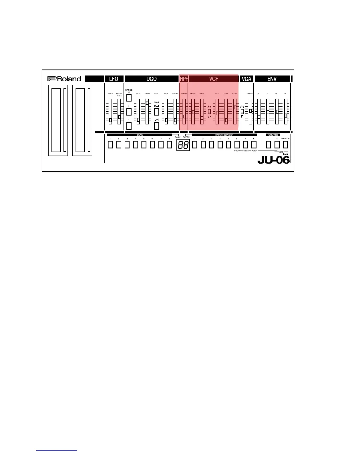
Voltage Controlled Filter
HPF
This filter lets the high frequency harmonics pass and cuts off the iow frequency harmonics. As this fitter is not
voltage controlled, Cutoff Point is changed by only moving the knob.
1. HPF Cutoff Frequency
This knob sets the Cutoff point of the HPF. With this set to 1, the DCO output passes the filter unprocessed, and as it
is raised, Cutoff point is heightened, higher harmonics being passed. In the meantime, at its lowest position "0", lower
frequencies are boosted. (This is specially useful for boosting bass sound of organ, etc.)
VCF
This filter changes the tone color by cutting off or emphasizing harmonics. This filter lets the low frequency harmonics
pass and cuts off the high frequency , and is controlled by a voltage.
2. FREQ • Cutoff Frequency Knob
This knob is to change the Cutoff Point of the VCF. As you lower the knob, higher frequency will be cut off, and the
sound will fade out when the waveform becomes nearest to Sine Wave.
3. RES • Resonance
This control emphasizes the Cutoff Point set by Cutoff Frequency knob ©. As you raise the knob, certain harmonics
are emphasized and the created sound will become more unusual, more electronic In nature. If you alter the Cutoff
Frequency Knob while the Resonance Knob is set to a high level, you can create a type of sound that is attainable
only from a synthesizer. If you raise the Resonance knob up to the maximum, the VCF will start its self oscillation.
4. ENV •" ENVELOPE MODULATION
When the Cutoff Point of the VCF is being modulated by the output of the Envelope Generator, this knob is used to
adjust the intensity of the modulation. You can change the Cutoff Point of the VCF in each note with the ADSR pattern
previously set. So the tone color within one note can be changed quite drastically.
5. POLARITY SWITCH
This is the selector switch for the polarity of the Envelope. When it is set at reverse polarity, the ADSR pattern will be
reversed and the tone color alteration will be the other way round.