17
Mar. 2010 SPD-30
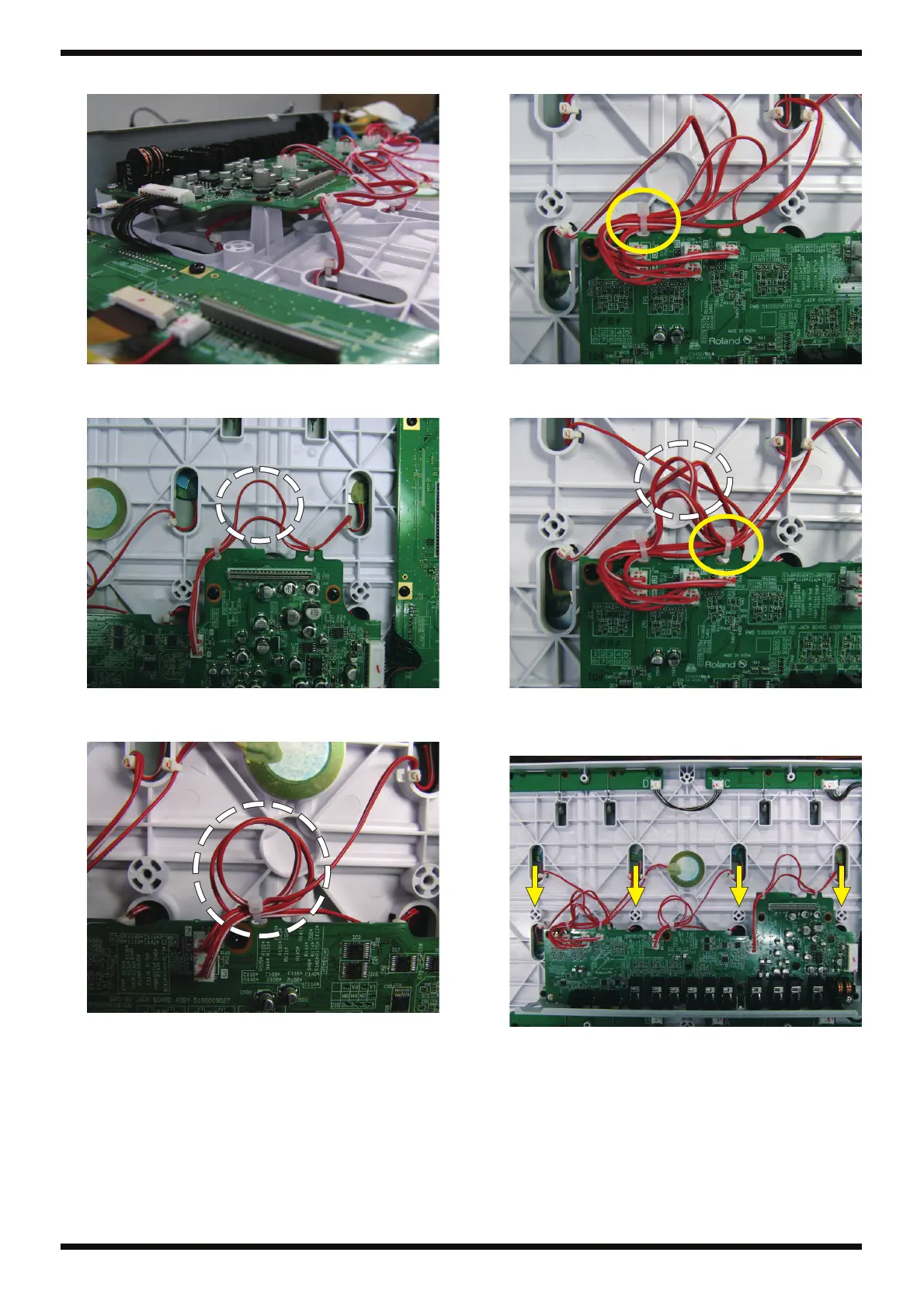
3. Arrange cable 5 as shown in the figure.
fig.bunaki-sensor-4.eps
4. Using cable ties, secure cables 4 and 8 in place as shown in the figure.
Arrange excess length as slack at the center.
fig.bunaki-sensor-5.eps
5. Using cable ties, secure cables 3 and 7 in place as shown in the figure.
Arrange excess length in a loop.
fig.bunaki-sensor-6.eps
6. Using a cable tie, secure cables 1, 5, 2, 6, and C at the hole on the left.
fig.bunaki-sensor-7.eps
7. Next, use a cable tie to secure in place at the hole on the right. Arrange
excess length as slack at the center.
fig.bunaki-sensor-8.eps
* Be careful to ensure that cables do not lie over any of the holes at the four
locations shown by the arrows. The screws for securing the Top Case and Bottom
Case pass through these.
fig.bunaki-sensor-9.eps
 Loading...