16
Mar. 2010 SPD-30
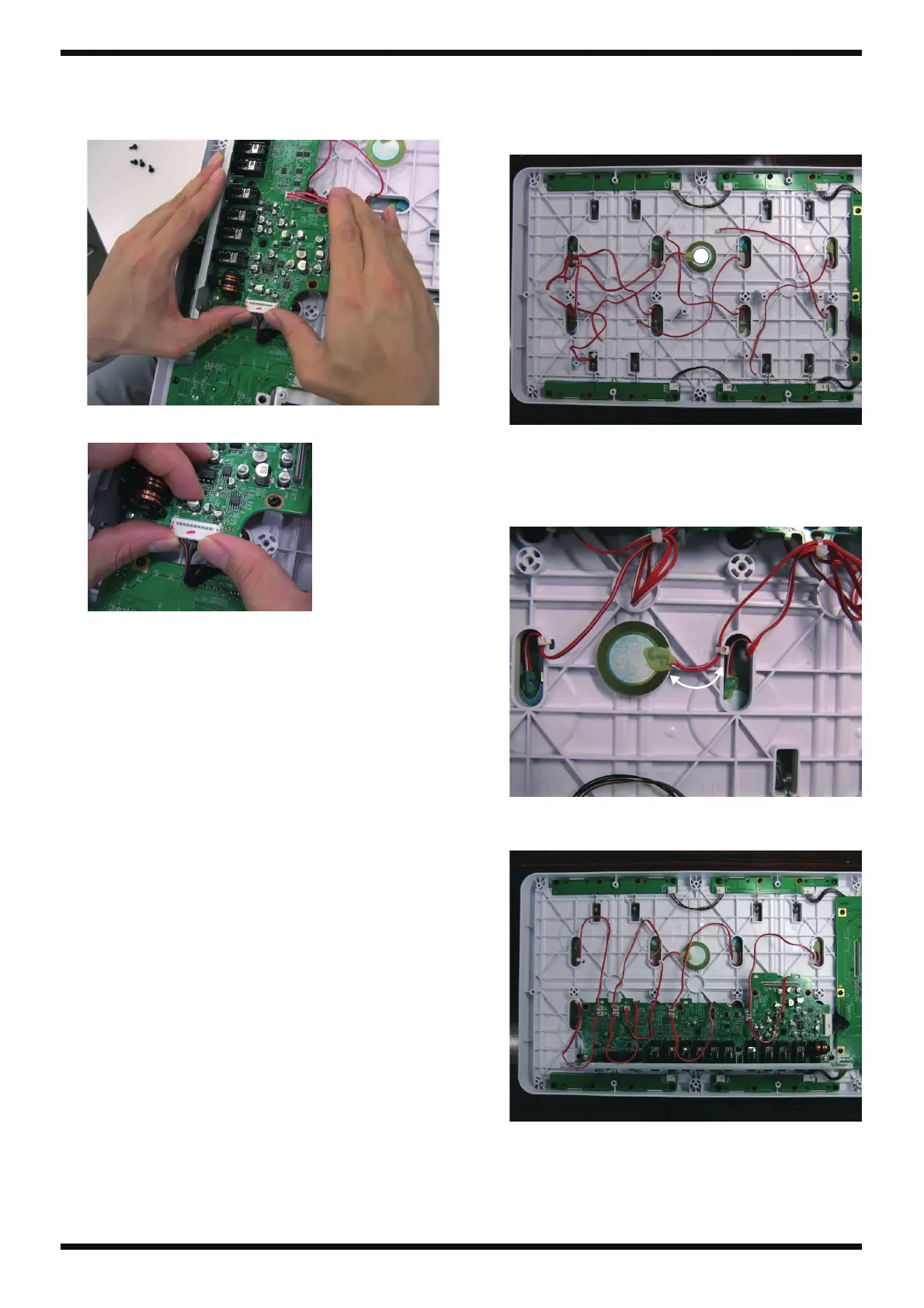
Connector Insertion on the Jack Board
When inserting the connector into CN5 on the Jack Board Assy, first place your
hands at the edges of the circuit board, then insert the connector.
fig.bunaki-CN-1.eps
* Keep your fingers away from the capacitors.
fig.bunaki-CN-2.eps
Connecting the Sensor Cables
On the service-use Top Case Assy (#5100010681), the cables extending from 1
through 8 in the figure are secured in place using cable ties. The cancel sensor
at C is not installed.
fig.bunaki-sensor-1.eps
1. Peel off the backing paper from the double-sided adhesive tape on the
underside of the Sensor Assy (#5100014741), and affix to the tab on the
underside of the Top Case.
Secure in place using a cable tie at a location 30 millimeters from the
edge of the sensor.
fig.bunaki-sensor-2.eps
2. Referring to the Wiring Diagram (p. 18), connect cables 1 through 8 and
C to the Jack Board Assy.
fig.bunaki-sensor-3.eps
C
1234
5678
30mm

 Loading...