NOV.Ist,
1982
SH-101
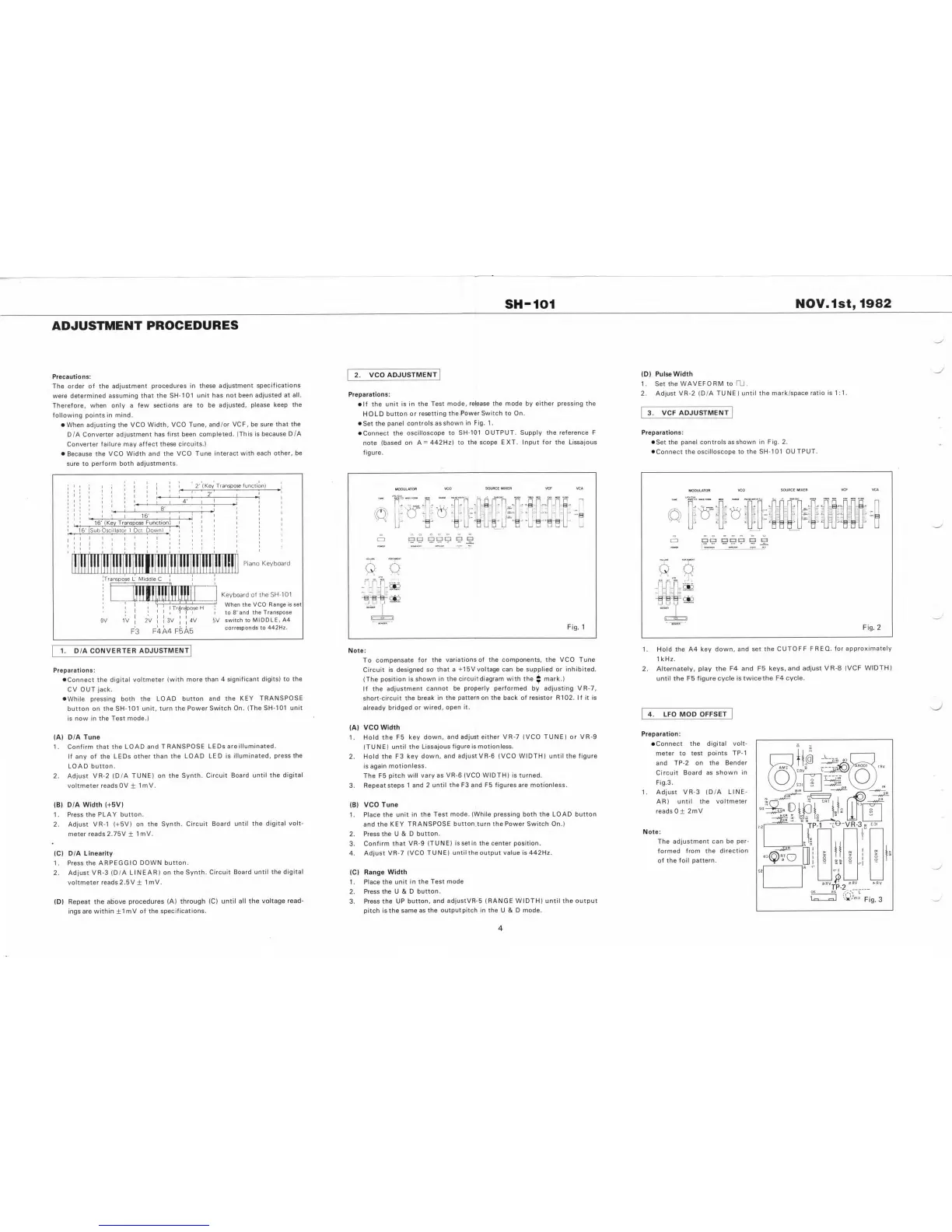
ADJUSTMENT
PROCEDURES
(D)
PulseWidth
Set the
WAVEFORM
to
rU_
Adjust VR-2 {D/A
TUNE) until the mark/space
ratio is
1:1.
2.
VCO
ADJUSTMENT
Precautions:
The order of the
adjustment procedures
in these
adjustment
specifications
were determined
assuming that the
SH-101 unit has
not been
adjusted at
all.
Therefore, when
only
a
few sections
are to be
adjusted,
please keep
the
following
points in mind.
•
When adjusting
the VCO Width,
VCO Tune,
and/or VCF, be
sure that
the
D/A Converter
adjustment has first
been completed.
(This is
because D/A
Converter
failure may affect these
circuits.)
•
Because
the VCO Width and
the VCO
Tune interact
with each
other, be
sure to
perform both
adjustments.
1
.
2
.
Preparations:
•
If the
unit is
in the Test
mode,
release the mode
by
either pressing the
HOLD
button
or resetting
the
Power Switch
to
On.
•
Set the
panel
controls
asshown
in Fig. 1
.
•
Connect
the
oscilloscope to
SH-101
OUTPUT. Supply the reference F
note
(based on
A
=
442Hz) to
the
scope
EXT. Input for the Lissajous
figure.
3. VCF
ADJUSTMENT
Preparations:
•
Set the panel
controls
as
shown in
Fig. 2.
•
Connect the
oscilloscope to
the SH-101
OUTPUT.
I
I
I
I
I
2'
(Key Transpose
function}
\
I
I
\
SOURCE MIXER VCF VCA
VCO
MODULATOR
VCF C
SOURCE MIXER
VCO
MODULATOR
I
I
I
I
I
2
'
I
I
MJl a
mett FOM
•A
rmo mt
juif O
wwc rotm
EMV WOO
ftrw
woe
T
meo
Mcs €MV
I
MOSC
t I
RAMCt
I
:
“
:
i
\ \
4
j.'
I
TUNC
4'
r.
i
I
m
iliil
nI
I
a_
Ol
8
' «
n
(T)'
O'
N.
i
1
o
I
I
I*
~
)
I r
4 «
L
il
13
I
1
16'
I
I
i
i
u‘"
'U-
I
f
\
\
\
I—
b-'
*
rt frl
‘
;
u
®
L
I
4
I
I
16'
(Key
Transpose Function)
I
t
I
I
u
II
16'
(Sub
Oscillator 1
Oct.
Down)
I
I
II
!
Q
a
t
!
a a
C3 o
1
130
BOO
E3
C3
I
I
i
I
i
*
I
I
r-
1
MMiOB
I
I
I
I
ti
(
I
I
I
VOiUW(
NT
»ONTAMCNT
VOiUWC
Piano
Keyboard
o o
«•
IPO
«<0 «Cf NOQ
lR-H-
c
- —
-
e?
0 o
I
I
I
I •
i
^
Transpose
L
Middle
C
iPO
I I
J
I
CO
Vt'
r 1
h
I
I
T
mt
Keyboard of
the SH-101
When the
VCO Range is set
to 8'and
the Transpose
5V
switch to
MIDDLE, A4
corresponds to
442Hz.
I
- J LI
. I
'
j
I
I
I
Tr^n^pose H
I
MNOCN
i
I
I
I
I
I
I I
1
I
3V
4V
I
I
I
Fig. 1
F4A4 F5A5
I
1 . Hold
the A4 key down,
and set the
CUTOFF
FREQ, for
approximately
1kHz.
2.
Alternately, play the F4
and F5 keys,
and adjust
VR-8 (VCF
WIDTH)
until the F5 figure cycle
Istwicethe
F4 cycle.
1.
D/A CONVERTER
ADJUSTMENT
Note:
To
compensate
for the
variations of the components, the VCO Tune
Circuit is
designed so
that a
+15V voltage can
be
supplied or inhibited.
(The
position is
shown in
the
circuit
diagram with the
J
mark.)
If the
adjustment
cannot
be properly performed
by
adjusting VR-7,
short-circuit
the
break in the
pattern on the back of resistor R102. If it is
already
bridged or
wired,
open it.
Preparations:
•
Connect the digital
voltmeter (with
more than 4
significant
digits) to the
CV OUT jack.
•
While pressing both
the LOAD
button and the
KEY
TRANSPOSE
button on the
SH-101 unit,
turn the Power
Switch On.
(The SH-101
unit
is now in the
Test mode.)
4.
LFO MOD
OFFSET
(A) VCO
Width
Hold
the F5 key
down, and adjust either VR-7 (VCO TUNE) or VR-9
(TUNE)
until the
Lissajous
figure
is motionless.
Hold
the F3 key
down,
and adjustVR-6 (VCO WIDTH) until the figure
is
again
motionless.
The F5
pitch will
vary as
VR-6
(VCO WIDTH) is turned.
Repeat
steps 1
and 2
until the F3 and F5 figures are motionless.
Preparation:
• Connect the
digital volt-
meter
to
test
points TP-1
and
TP-2 on the
Bender
Circuit Board as
shown in
Flg.3.
1. Adjust
VR-3 (D/A
LINE-
AR) until
the voltmeter
reads
0
±
2mV
(A) D/A Tune
Confirm that
the LOAD
and
TRANSPOSE LEDs are
illuminated.
If any of the
LEDs other
than the
LOAD LED is
illuminated,
press the
LOAD
button.
Adjust
VR-2 (D/A TUNE)
on the Synth.
Circuit
Board until the
digital
voltmeter reads
OV
±
ImV.
1
.
1
.
2 .
2 .
3.
(B) D/A
Width (-f5V)
Press the
PLAY button.
Adjust
VR-1 (-I-5V) on
the Synth.
Circuit
Board until the
digital
volt-
meter reads 2.75V
±
1 mV.
(B) VCO
Tune
1.
Place the
unit in
the Test
mode.
(While pressing both the LOAD
button
and
the KEY
TRANSPOSE button.turn the Power Switch On.)
2.
Press the U &
D
button.
3.
Confirm
that VR-9
(TUNE)
issetirt
the center position.
4.
Adjust VR-7
(VCO
TUNE)
until
the output
value is 442Hz.
1
.
2 .
Note:
The
adjustment can be
per-
formed from the
direction
of the foil
pattern.
(C)
D/A Linearity
1 . Press the
ARPEGGIO
DOWN button.
2. Adjust VR-3
(D/A
LINEAR) on the
Synth. Circuit
Board until
the
digital
voltmeter
reads 2.5 V
±
ImV.
(C)
Range
Width
Place the
unit in
the Test
mode
Press
the U & D
button.
Press the
UP button,
and adjustVR-5 (RANGE WIDTH) until the output
pitch is the
same as the
outputpitch
in
the
U &
D mode.
1 .
2 .
(D) Repeat
the above
procedures (A)
through (C)
until all the
voltage
read-
ings are
within
±1
mV of the
specifications.
3.
4