Do you have a question about the Roland SH-5 and is the answer not in the manual?
Describes the KB-1 unit and its subdivisions.
Lists subdivisions of the CU-1.
Details circuits on OP-19 board.
Describes VCO-1 operation and wave shaping.
Covers VCO-2 and Ring Modulator circuits.
Explains signal routing and external input amp.
Details VCF, BPF, and VCA circuits.
Explains AR, ADSR, and Fixed Env. circuits.
Covers output jacks and external control inputs.
Describes power supply unit and voltage accuracy.
Guidance on fuse replacement and issues.
Notes on calibration order and accuracy.
Importance of correct slide switch positioning.
Using specified parts for stability and damage prevention.
Details the SK-142B keyboard assembly components.
Details the PB-1 bender assembly components.
Details OP-25A manual board assembly components.
Details the CU-1 circuit diagram.
Details OP-19A circuit board components.
Details OP-19B circuit board components.
Provides circuit diagram for OP-19B.
Details VO-3 board assembly.
Details VO-3A board assembly for serial numbers 450400 to 490949.
Details VO-3B board assembly for serial numbers 500950 and higher.
Details OP-20A circuit board components.
Details OP-20B circuit board components.
Provides circuit diagram for OP-20B.
Details OP-23A mixer board assembly.
Provides circuit diagram for OP-23A.
Details OP-21B circuit board assembly.
Provides circuit diagram for OP-21B.
Details OP-22 circuit board components.
Details OP-22A circuit board components.
Provides circuit diagram for OP-22A.
Provides the circuit diagram for the PC-5A power supply.
Details the PS-23A power supply board assembly.
Adjusts ±14V and ±10V power supply voltages.
Adjusts LFO-1, LFO-2, and Sample/Hold circuits.
Adjusts noise generator and keyboard key voltage.
Adjusts bender voltage and VCO parameters.
Adjusts VCO-1 output frequency using methods.
Covers VCO-2 and Ring Modulator adjustments for OP-20.
Covers VCA and VCF adjustments for OP-21.
Covers VCF, HPF, and ADSR adjustments for OP-22.
Parts for OP-25A manual board.
Parts for OP-19B circuit board.
Parts for OP-23A mixer board.
Parts for OP-21B circuit board.
Parts for OP-22A circuit board.
Parts for PS-17A power supply board.
Parts for PS-23A power supply board.
| Brand | Roland |
|---|---|
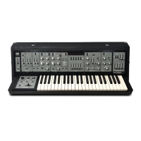
| Model | SH-5 |
| Category | Synthesizer |
| Language | English |