Page | 45
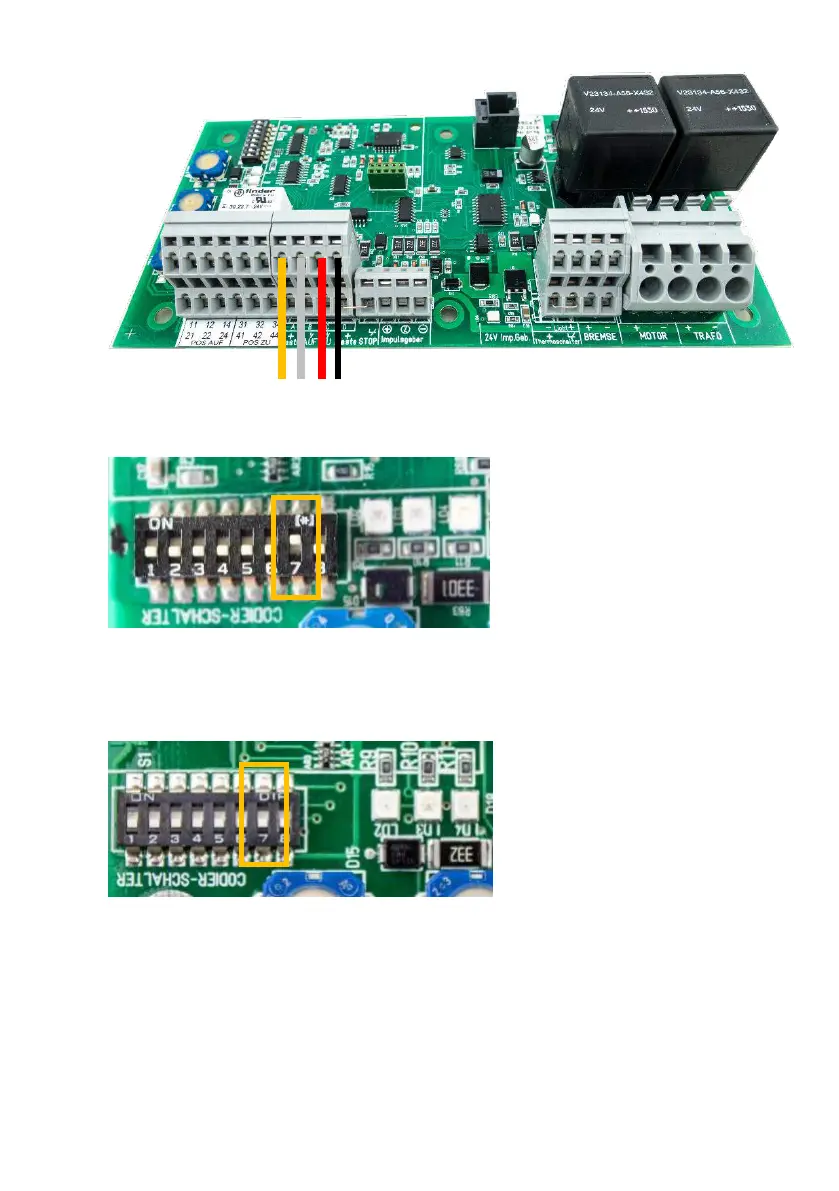
3. Connect the switch connections: A, B, C, D with RSC circuit board: A, B, C, D.
4. Operation with PS1 key switch
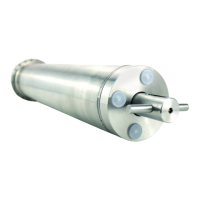
Switch DIP switch no. 7 on the RSC controller to the ‘ON’ position.
Power may be supplied to the RSC circuit board again only after this step.
5. Operation without the PS1 operating switch
Leave DIP switch no. 7 in the ‘OFF’ position.