Do you have a question about the Rollo Solar RT 200 and is the answer not in the manual?
Covers electrical connections, installations, and safety precautions for electrical work.
Procedures for starting up the system and providing instructions to the operator.
Details delivery contents, checks, and lists required installation tools.
Explains the function of various safety devices protecting the user.
Defines the appropriate applications and conditions for Rollo Solar motors.
Provides general installation guidelines and electrical work precautions.
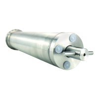
Step-by-step guide for installing the RT 200 motor in the shaft.
Step-by-step guide for installing the RT 400 motor in the shaft.
Instructions for converting from a K-motor to an RT drive using an adapter.
Guide on properly routing cables between the drive and clamping flange.
Detailed steps for installing the counter bearing to lock the shaft.
Guide on preparing the distribution box for cable connections and grounding.
Instructions for installing the flexible tube onto the pre-assembly flange.
Guide on inserting the drive cable into the distribution box.
Instructions on using the cable gland for the drive cable.
Guide on inserting cables between the distribution box and the technical system.
Table detailing required cable cross-sections for different lengths and applications.
Wiring diagrams for connecting the RT drive with 7 or 9 cores.
Wiring diagrams for connecting the RT drive with 5 or 9 cores.
Instructions on using the cable gland for distribution box and transformer connections.
Steps for grounding the distribution box according to DIN standards.
Guide on connecting the drive cable to the connecting cable.
Describes an alternative method for routing the cable through the distribution box.
Instructions for sealing the distribution box using gel to prevent water ingress.
Guide on placing the cover on the distribution box after sealing.
Identifies components of the transformer and motor fuse, and provides installation caution.
Instructions for replacing a defective motor fuse with a new one of the same rating.
Guide on connecting the controller with cables, noting EPROM retention.
Detailed image and labels of the RSC 3 circuit board.
Detailed image and labels of the RSC 4 circuit board with PS1.
Comprehensive circuit diagram for RSC3 and RSC4 controllers.
Instructions for configuring the DIP switch for public pools, especially the kill switch.
Guide on connecting the braking resistor, noting its variation with motor power.
Identifies status LEDs and their meanings.
Details the internal programming and operating buttons.
Steps to configure the 'ZU' (CLOSED) end position by activating programming mode.
Steps to configure the 'AUF' (OPEN) end position by activating programming mode.
Guide on connecting and identifying parts of the key switch.
Guide on connecting the PS1 switch, including cable characteristics and switch operation.
Guide on connecting the RSC wireless module and its components.
Instructions for teaching handheld transmitters to the receiver.
Explains the connection for locking the filter pump based on roller shutter positions.
Diagram and description for connecting the controller with a BUS/EIB system.
Troubleshooting steps for end positions not stopping correctly.
Troubleshooting steps for when the switch or programming switch is not working.
Troubleshooting steps for when the handheld transmitter or remote control is not working.
Troubleshooting for controller programming, emergency mode, and thermosensor issues.
Troubleshooting for motor or pulse generator faults displayed on the circuit board.
Troubleshooting steps for undervoltage errors detected by the system.
Steps to activate emergency mode by holding the PROG button.
Steps to deactivate emergency mode by holding the PROG button.
Information regarding maintenance requirements for Rollo Solar underwater drives.
Instructions for decommissioning the underwater drive by a skilled expert.
Guidelines for proper disposal of the motor, advising against household rubbish.
| Brand | Rollo Solar |
|---|---|
| Model | RT 200 |
| Category | Engine |
| Language | English |