Seite /
Page
- 25 -
28.03.1996 / PT / Rev 00
Feuerlöschpumpe R600
Fire Pump R600
© 1996
Technische Beschreibung
Technical Description
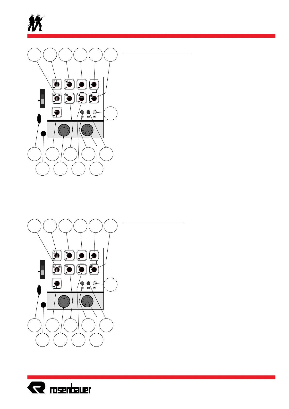
Armaturen und Betätigungen
H8 Kontrollampe: Nebenabtrieb (Pumpe) eingeschaltet *
H9 Kontrollampe: Entlüftungspumpe eingeschaltet *
H10 Kontrollampe: Schaummitteltanksaugventil offen *
P28 Manometer (effektiver Wasserdruck druckseitig)
P30 Manovacuummeter
S3 Schalter für Entlüftungspumpe *
S6 Schalter: Schaummitteltanksaugventil *
S11 Schalter: Wassertanksaugventil AUF/ZU *
S14 Wahlschalter: Einstellung der Zumischrate *
S17 Schalter: Wassertankfüllen über die Pumpe *
S35 Schalter: Niveauregelung für Wassertankinhalt *
S44 Schalter: Druckabgang links *
S45 Schalter: Druckabgang rechts *
S53 Schalter: Intern Spülen der Pumpenanlage *
Z4 Handgas
Z7 Betätigung: Pumpenentleerung *
Die Anordnung der Schalter und Kontrollampen kann auf Grund
von Sonderwünschen von der Abbildung abweichen.
S53S45S44S35
+-
I
0
I
0
I+
I
0
I
0
I
0
0
I
0
I
0
3%
6%
8%
ND
AUSGANG
LINKS
ND
AUSGANG
RECHTS
S11 S3
Z4
Z7
S14
P30
S6
S17
H8
P28
H9
H10
Controls and connections
H8 pilot lamp: P.T.O. (pump) engaged *
H9 pilot lamp: priming pump engaged *
H10 pilot lamp: foam compound tank suction valve open *
P28 pressure manometer (actual value)
P30 manovacuummeter
S3 switch for priming pump *
S6 switch: foam compound tank suction valve *
S11 switch: water tank suction valve OPEN/CLOSE *
S14 selector switch: adjustment of foam admixing rate *
S17 switch: water tank filling via pump *
S35 switch: automatic tank level control *
S44 switch: pressure outlet left hand side *
S45 switch: pressure outlet right hand side *
S53 switch: internal flushing of pump installation *
Z4 manual throttle control
Z7 linkage: pump drainage *
The location of switches and pilot lamps may differ from drawing
due to optional equipment.
S53S45S44S35
+-
I
0
I
0
I+
I
0
I
0
I
0
0
I
0
I
0
3%
6%
8%
ND
AUSGANG
LINKS
ND
AUSGANG
RECHTS
S11 S3
Z4
Z7
S14
P30
S6
S17
H8
P28
H9
H10
 Loading...