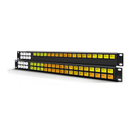
16 • Hardware Overview RCP-ME User Guide (v4.0)
Figure 1.4 Examples of a Message Screen
Error Screen
An error screen appears briefly when the routing switcher sends a response back to the RCP-ME indicating that it
cannot complete the request.
Figure 1.5 Examples of an Error Screen
Rear Panel Overview
Each rear panel provides a power supply connection and an ethernet port.
Figure 1.6 Rear Panel of an RCP-ME
1. PSU Connection
There is one power supply connector located on the rear of each RCP-ME. This connector requires a +5VDC
connection to an external power supply.
2. Ethernet Port
An ethernet connection is required for RCP-ME operation.
The Ethernet port is an RJ45 connector used to connect the panel to an external Ethernet network. This port has
its RJ45 connector wired as a Network Interface Card (NIC).
Notice — The RCP-ME automatically powers on when power is applied.
Notice — The Ethernet port does not support Power-over-Ethernet (PoE).
1234
SRC: TAKE ?
**** NO RESP ****
+5V
ETHERNET
 Loading...