18 • Getting Started RCP-ME User Guide (v4.0)
System Overview
A routing switcher system may use distributed control across the internet, a LAN, or a VPN. The routing switcher
system shown in Figure 2.1 has been simplified.
Figure 2.1 Layout showing a simplified routing switcher system with an RCP-ME
All ethernet connections use standard CAT5/5e/6 Ethernet cables.
How the RCP-ME and Routing Switchers Communicate
The RCP-ME can operate in two distinct modes; physical and virtual. In physical mode switching, the RCP-ME
sends switch requests directly to the routers (via NK-NET, NK-IPS). The router/s respond via the same method to
the RCP-ME and the RCP-ME updates its display according to the result.
Virtual mode switching informs NK-VRC, Ultrix router or Ultricore Central Controller of the switch request, and
they in turn issue physical switch requests to the router/s
Physical mode switching restricts SRC button 1 to be physical IN 1 on a router when used with an NK series router.
Virtual mode switching removes this restriction and NK-VRC, Ultrix routers or Ultricore Central Controller
devices can 'map' this source #1 command to one or more unrelated physical inputs sockets.
The RCP-ME stores information on the menu, destination, level, breakaway (when used with an NK series router),
and machine control status. The routing switcher stores the crosspoint status in its internal memory.
T-BUS
Network Switch
PORT 2 PORT 3 PORT 4 PORT 5 PORT 6 PORT 7 PORT 8PORT 1
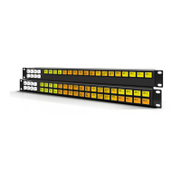
Ultrix
32x32 3G/HD/SD SDI Router
ENET 2
ENET 1
14
A B
REF
1 2 3 4 5 6 7 8910 11 12 13 14 15 16 1 2 3 4 5 6 7 8 9 10 11 12 13 14 15
16
AUX A AUX B
OUT IN
1 2 3 4 5 6 7 8910 11 12 13 14 15 16 1 2 3 4 5 6 7 8 9 10 11 12 13 14 15 16
AUX A AUX B
OUT IN
Ultrix-HDNBC-IO
REF
!
ETHERNET
RCP-ME
Remote Control Panel
PSU
ETHERNET
RCP-ME
Remote Control Panel
PSU
PC running DashBoard
Internet / LAN / VPN
Ethernet Communication
Router Inputs
Router Outputs
Ultrix
64x64 3G/HD/SD SDI Router
ENET 2
ENET 1
14
A B
REF
1 2 3 4 5 6 7 8910 11 12 13 14 15 16 1 2
3
4
5
6 7 8 9 10
11
12 13
14
15
AUX A AUX B
OUT IN
1 2 3 4 5 6 7 8910 11 12 13 14 15 16 1 2 3 4 5 6 7 8 9 10 11 12 13 14 15 16
AUX A AUX B
OUT IN
Ultrix-HDNBC-IO
REF
REF
1 2 3 4 5 6 7 8910 11 12 13 14 15 16 1 2 3 4 5 6 7 8 9 10 11 12 13 14 15
16
AUX A AUX B
OUT IN
1 2 3 4 5 6 7 8910 11 12 13 14 15 16 1 2 3 4 5 6 7 8 9 10 11 12 13 14 15
AUX A AUX B
OUT IN
Ultrix-HDNBC-IO
Ultrix-HDNBC-IO
16
16
!
!
!
VTR 1
Server 2
Server 3
VTR 2
Camera 1
Camera 2
Multiviewer
Server 1
 Loading...