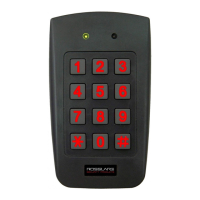
Controller Operation
46 AYC-F/Gx4 Series Installation and Programming Manual
output. When in use, the auxiliary output is normally open and the
door sensor functions normally. When a valid code is entered, the
auxiliary relay shunts the door sensor for the duration of the shunt
time, as defined by the auxiliary setting. If the door is left open longer
than the shunt time, an alarm is triggered.
5.9.9.6 Auxiliary Mode 5
Auxiliary input function: Door Monitor
Auxiliary output activated by: Shunt (explanation below)
For example, in Auxiliary Mode 5, the controller is capable of shunting
an alarm system. In this mode, the auxiliary input is to be wired to the
magnetic contact switch on the door. The auxiliary relay is wired to
the alarm system. Without a valid code entered, the auxiliary relay
matches the condition of the magnetic contact switch; if the door
opens, the auxiliary relay opens; if the door closes, the auxiliary relay
closes. When a valid code is entered, a countdown for maximum
shunt time, as defined by the auxiliary setting, begins; if the door is
not closed before the maximum shunt time, the alarm is triggered.
5.9.9.7 Auxiliary Mode 6
Auxiliary input function: Door Monitor
Auxiliary output activated by: Forced entry
For example, in Auxiliary Mode 6, the controller can trigger the
auxiliary relay if the door has been forced. If the siren settings are
enabled, the siren is activated.
In this mode, the auxiliary input functions as a door monitor switch
and is wired to the magnetic contact switch on the door. The auxiliary
relay is to be wired to the alarm system. If the door is forced open,
the controller waits for the period of the forced door delay time to
elapse and then it activates the auxiliary relay. The auxiliary setting
sets the forced door delay period.
 Loading...