4
Fig. 2a
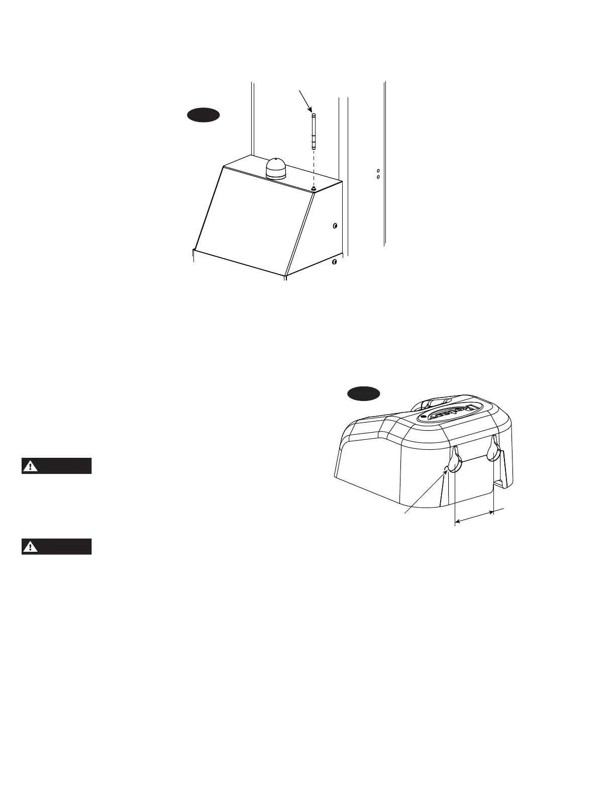
6. Install Antenna: Remove antenna from packaged location
(taped to control box) and install as shown, Fig. 2.
Antenna
Fig. 2
7. Confirm battery charger is turned ON.
8. Close lift door and re-install M8 BHCS removed earlier.
9. Screw M20 bolt and M10 socket head bolts clockwise on
wheel jack and front of superstructure to adjust unloaded
column ground clearance, Fig. 1. Ground clearance is
determined by how far the bolts are turned. When the
column is loaded, it will automatically lower to the floor.
Permit only trained personnel to operate
lift. After reviewing these instructions, become familiar
with the lift controls by running the lift through a few cycles
before loading a vehicle on lift. Observe and heed SAFETY
and WARNING labels on the lift.
This motor has internal arcing or sparking
parts. To minimize the Risk of Explosion, DO NOT expose to
flammable vapors.
OPERATING CONDITIONS: Lift is not intended for outdoor
use or storage and has an operating ambient temperature
range of 41º-104ºF (5º-40ºC). This product is intended for
indoor use only in a dry location.
DO NOT use lift in a manner other than intended. Included
(but not limited to) examples of unapproved uses of the lift
are: lifting vehicle by only one side, lifting different axles
with a column pair (lifting on the diagonal), and lifting non-
approved items.
10. Charging dock to be powered by 100-240V AC
50/60hz. Dock can be set on workstation or mounted
on wall, Fig. 2a.
1-3/4”
Suggested
3/8” or #10
Screws
11. Charger light (located on charger plug):
a.) Harding Charger: (ID-1000-08400)
i.) Blinking light indicates charging.
ii.) Solid light indicates fully charged.
iii.) No light indicates not charging.
b.) (XS-0841000H)
i.) Solid green indicates fully charged/not
charging.
ii.) Solid red indicates charging.
 Loading...