3
CAUTION
Keep hands clear
of yoke ends
during lift
operation.
Fig. 2
OPERATING INSTRUCTIONS
Fig. 3
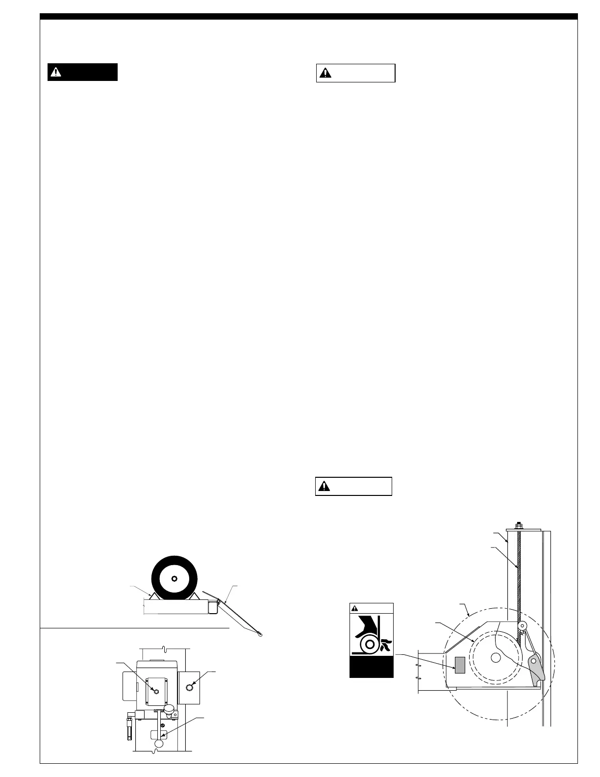
Triangular
Wheel Stops
Rear Wheel
Chock
Fig. 1
CAUTION
CAUTION
WARNING
To avoid personal injury and/or
property damage, permit only trained
personnel to operate lift.
After reviewing these instructions, get familiar with lift
controls by running the lift through a few cycles before
loading vehicle on lift.
Observe and heed SAFETY and WARNING labels on
the lift.
1. Loading: Lift must be fully lowered and no one in
service bay while the vehicle is brought on lift.
2. If lift is equipped with rolling jacks, jacks must be
fully lowered and the rear jack pushed toward center
of lift to provide under car clearance.
3. Drive vehicle onto lift and stop when vehicle's front
wheels are centered on turning radius gauges. On
lifts not used for wheel alignment, stop vehicle when
it is centered on runways. At all times, be sure rear
wheels are forward of the ramp/chocks and the ramp/
chocks will clear tires when the lift is raised, Fig. 1.
Driver and passengers must exit before raising.
4. Place triangular wheel chocks on each side of one of
the rear tires, Fig. 1.
5. To Raise Lift: Push the "RAISE" button on the
power unit. Release button at desired height, Fig. 2.
6. For Rolling Jack Operating Instructions see Rolling
Jack Installation, Operation and Maintenance
Instructions in the rolling jack shipping carton.
7. Before Lowering Lift: Be sure no one is in the lift
area and that all tools, tool trays, etc. have been
removed from under the lift and vehicle.
Latch Release
Air Button
LOWERING
Handle
RAISE
Button
The runways, ramps and connecting
yokes at each end of lift are designed
to rest on the floor when fully lowered. Observe
pinch point warning decals, Fig. 3.
8. Repeat Step 2.
9. To Lower Lift: If lift has been resting on the locking
latches, lift must be raised high enough for all four
latches to clear the latch plate slots inside the
columns.
10. Actuate the latch release air button on power unit to
disengage all four locking latches, Fig. 2. Hold
button in until lift has fully lowered.
Note: If button on air valve is released, the latches will
automatically reset to the engaged position.
11. Push the lowering handle on the power unit to lower
lift, Fig. 2. Lowering speed can be controlled by the
force applied to the lowering handle.
12. Observe lift and vehicle to be sure lift is level while
being lowered. If not, STOP repeat Steps 10
through 13.
13. Fully lower lift, remove the triangular wheel chocks
and check to be sure area is clear before removing
vehicle from lift, Fig. 1.
14. If your lift is not operating properly, DO NOT use
until adjustments or repairs have been made by
qualified lift service personnel.
Keep hands clear of yoke ends while the
lift is being raised or lowered, Fig. 3.
Column
Cable
Yoke End
Sheave
 Loading...