2
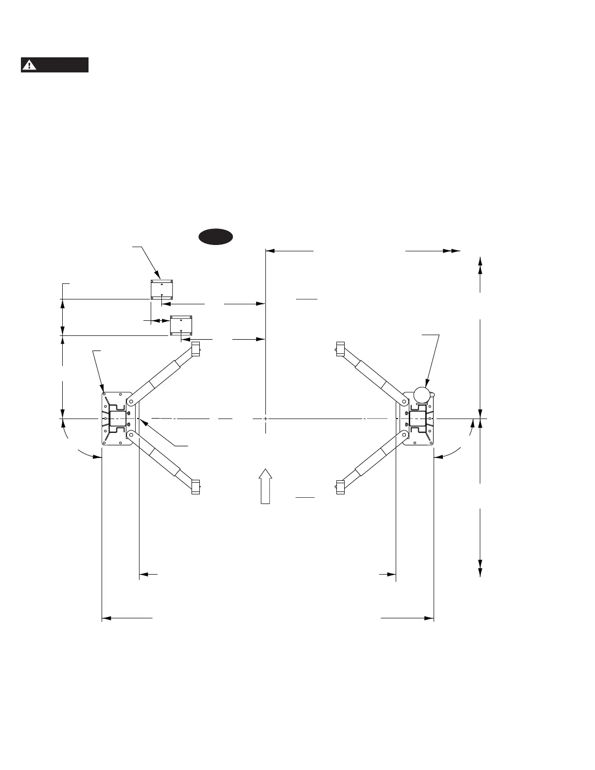
1. Lift Location: Use architects plan when available to
locate lift. Fig. 1 shows dimensions of a typical bay layout.
DO NOT install this lift in a pit or
depression due to fire or explosion risks. A forklift is
recommended to upright each column during installation.
Note: Installation tip - Upright each column after installing
column extensions, column ties, and overhead brackets.
Check to verify both columns are greased with Tuffoil
Lightning Grease at slider block points of contact inside
the columns (see greasing locations in Fig. 3). If columns
are not greased with Tuffoil Lightning Grease, apply at
greasing locations specified.
Fig. 1
HCAORPPA
Rear
Front
Lift
161" Outside of Baseplate to Outside Baseplate
167" Outside of Baseplate to Outside Baseplate
155" Narrow Outside of Baseplate to Outside Baseplate
111-3/8" Standard Drive Through Setting
117-3/8" Wide Drive Through Setting
105-3/8" Narrow Drive Through Setting
15'– 0" Min. To
Nearest Obstruction
90
0
Power Unit to
Passenger Side
15'– 0" Min. To
Nearest Obstruction
3/4" Anchors
(7) Per Side
7''– 6" Min. To Nearest
Obstruction
90
0
62 7/16"
19 1/4”
Wheel Spotting Dishes
6"
34"
28"
Alignment Notches
C
L
115" Standard Inside of Baseplate to Inside Baseplate
121" Wide Inside of Baseplate to Inside Baseplate
109" Narrow Inside of Baseplate to Inside Baseplate
2. Lift Setting: Position columns in bay using dimensions
shown in Fig.1. Place column with power unit mounting
bracket on vehicle passenger side of lift. Both column
base plate backs must be square on center line of lift.
Notches are cut into each base plate to indicate center
line of lift.
Use appropriate equipment to raise carriage to first latch
position. Be sure locking latch is securely engaged.
 Loading...


