3
(4) 3/8”-16NC x 1/2” Lg.
Flanged HHCS
(3) 1/4”-20NC x 5/8” Lg.
Flanged HHCS
(3) 1/4”-20NC Lg.
Flanged Lock Nut
Grease
Location
Grease
(4) 3/8”-16NC x 1” Lg.
Flanged HHCS
(4) 3/8”-16NC
Flanged Lock Nut
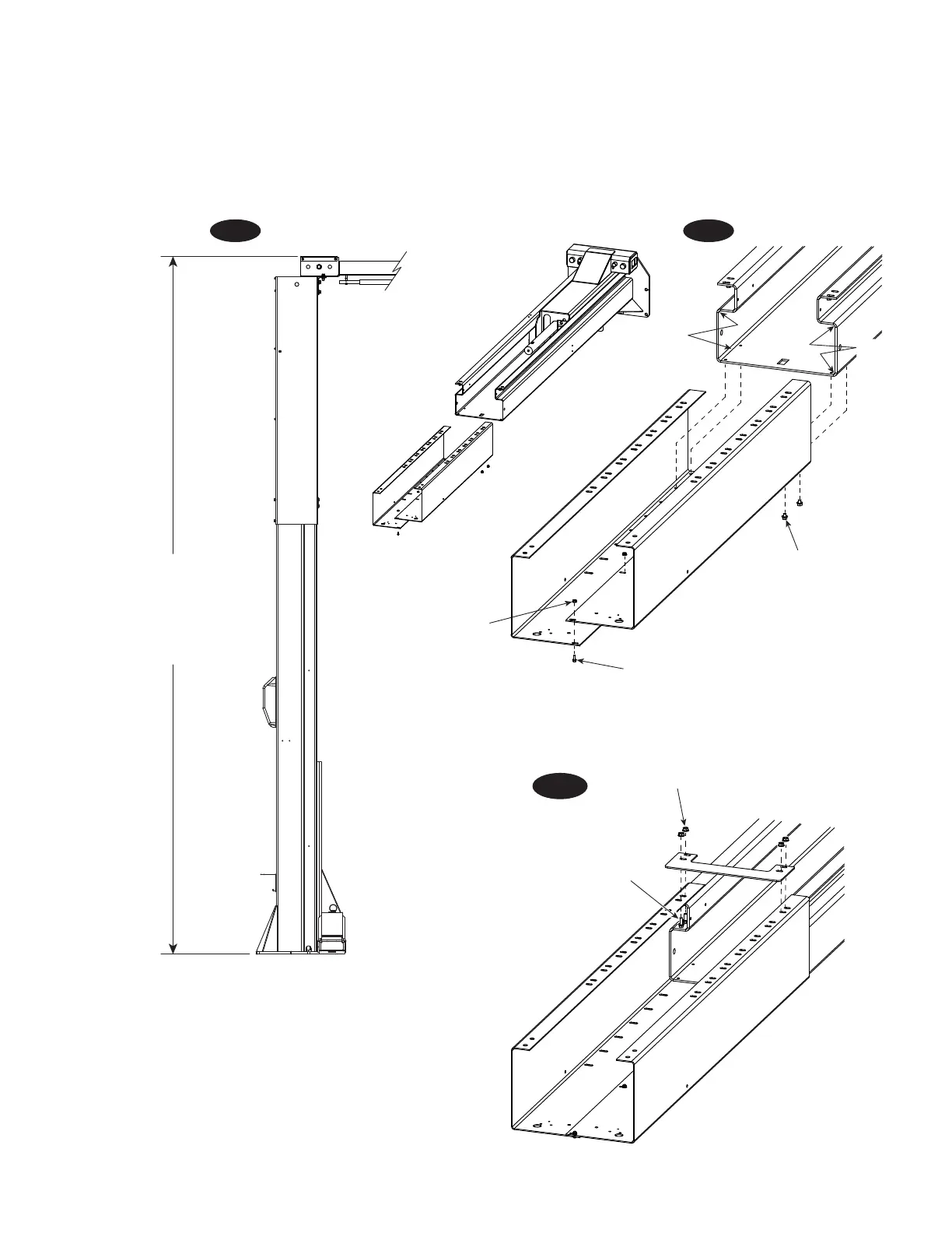
Extensions are adjustable
in 6” increments from 15’
to 16’-6” for Standard
models and from 13’-6” to
14’-6” for LC models.
Fig. 2
Fig. 4
3. Lift Height: See Fig. 2 for overall lift height of each
specific lift model. Add 1” min. to overall height to lowest
obstruction.
4. Install Column Extensions to columns using (4) 3/8"-
16NC x 1/2" Lg. Flanged HHCS and (3) 1/4"-20NC x 5/8" Lg.
Flanged HHCS with (3) 1/4"-20NC Lock Nut, Fig. 3.
Install column ties using (4) 3/8"-16NC x 1" Flanged HHCS,
Fig. 4 and (4) 3/8"-16NC Flanged Lock Nuts. Adjust column
extensions square and tighten hardware.
Fig. 3
 Loading...


