8
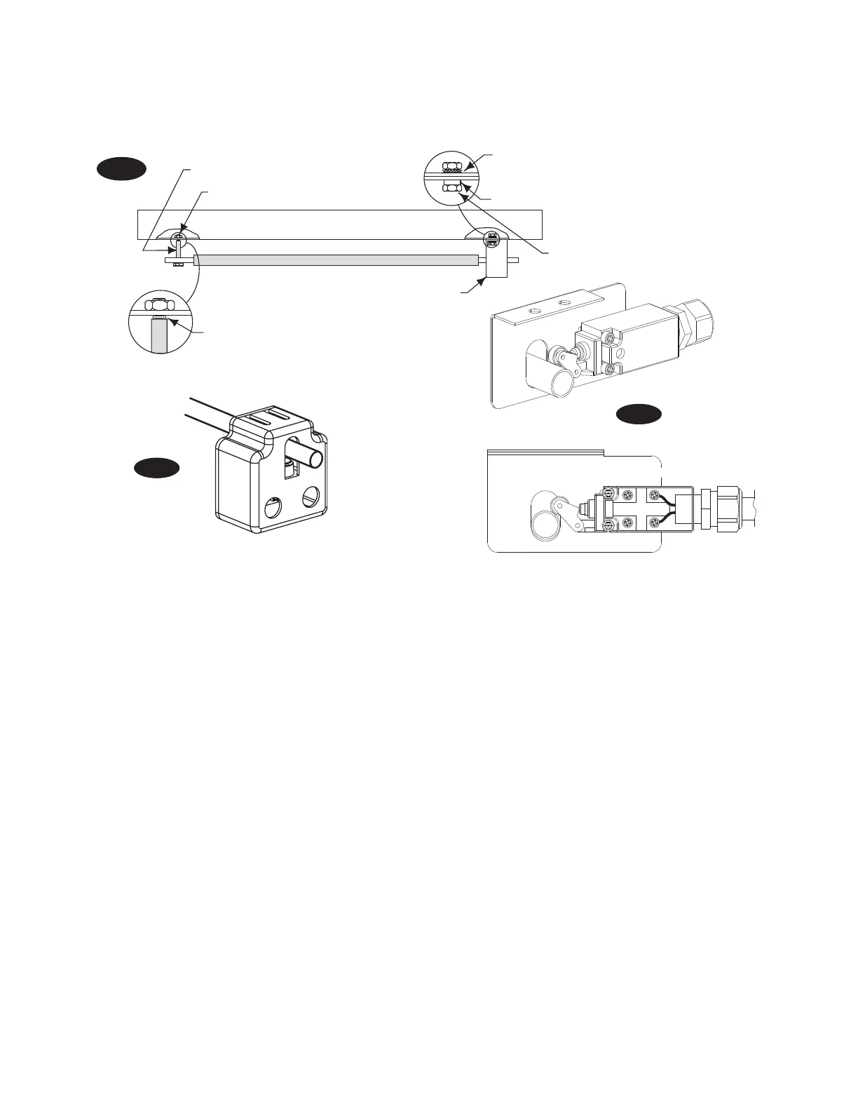
Fig. 7
(2)--3/4" Spacers
1/4"-20NC x 2-3/4" HHCS & Locknut
Star Washer
Flat Washer
(2) 1/4”-20NC-3/4” HHCS
Overhead Switch
1/16" Gap
Fig. 7a
Fig. 7a
8. Mount Switch assembly towards power unit column
as shown, Fig. 7, using (2) 1/4"-20NC x 3/4" lg. HHCS, nuts
and Washers.
Insert 1/4"-20NC x 2-3/4" HHCS through pivot hole in end
of switch bar. Insert opposite end of bar through slot in
switch mounting bracket, Fig. 7a. Then secure HHCS and
Switch Bar to overhead as shown, Fig. 7, using (2) 3/4"
spacers and 1/4”-20NC Locknut. Tighten Hex bolt leaving
1/16” gap between the spacer and the overhead assembly.
COVER NOT SHOWN
 Loading...