11
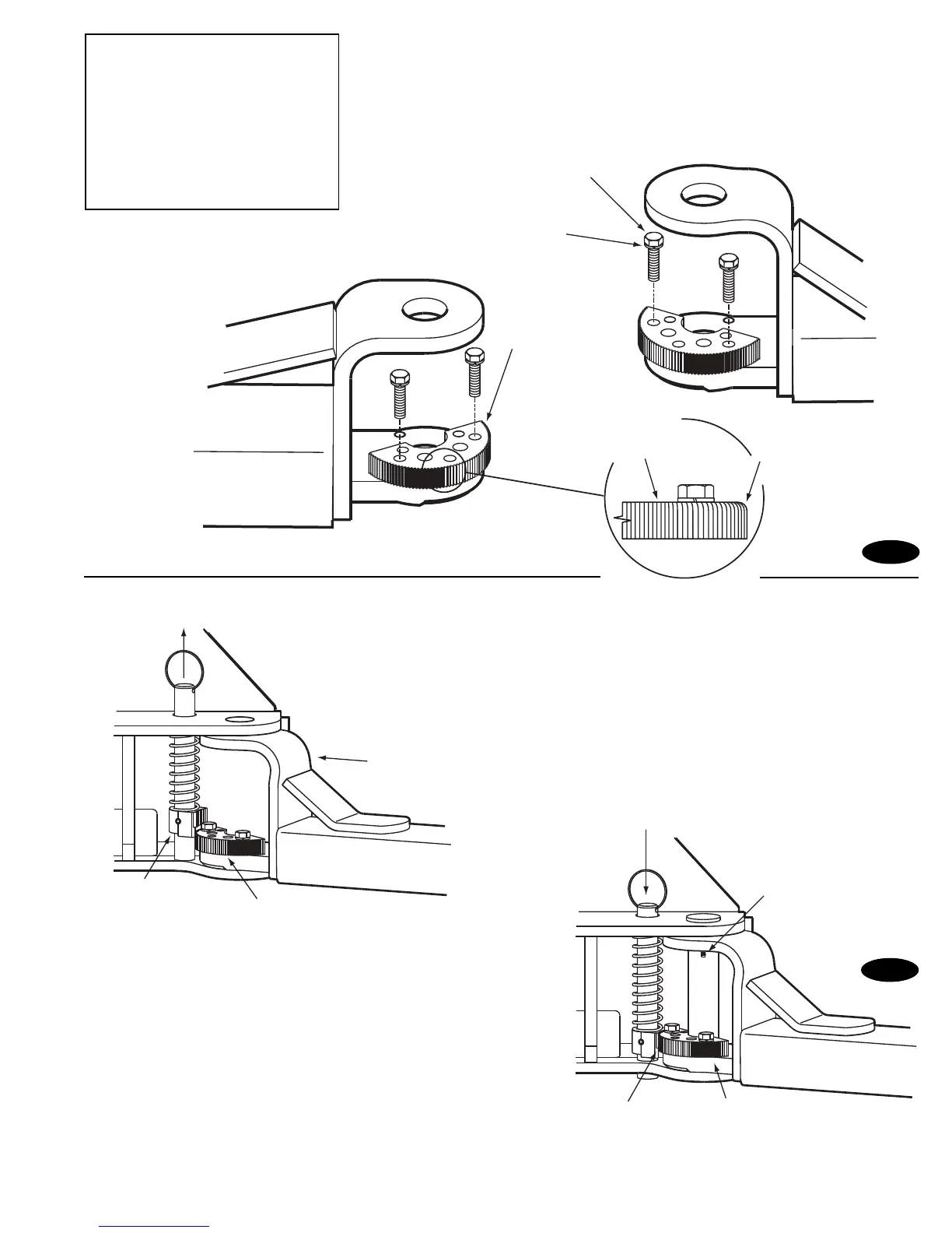
Left Rear & Right Front Arms
Right Rear & Left Front Arms
(8) 3/8-16NC x 1-1/2" lg. HHCS
(8) 3/8" Spring Lockwashers
Restraint Gear
Rounded
Edge Up
"TOP" will be
marked on top side
of restraint gear
Pull up on ring to
raise Gear Block.
Arm slides into yoke
clevis and under
Gear Block
Gear Block
Restraint Gear
Release and lower pin
to activate restraint.
3/16 x 2" Cotter Pin
Restraint Gear
Gears will mesh
together, closing
clearance gap.
NOTE: Once arm is installed in
yoke, pull up actuator pin and
swing arm fully around, being sure
that the Restraint Gear and Gear
Block always stay aligned. If they
do not stay aligned, remove
restraint gear and install in the
opposite position.
Fig. 17
Fig. 18
NOTE: To check operation of arm restraints, raise
carriage 1 min. from full down position. Pull up on
pin-ring and adjust arms to desired position. To engage
restraint, let pin-ring down allowing gear teeth to mesh
together. It may be necessary to rotate arm slightly to
engage gear teeth.
NOTE: Pin & Ring, Spring, & Gear Block are all preassembled.

 Loading...


