8
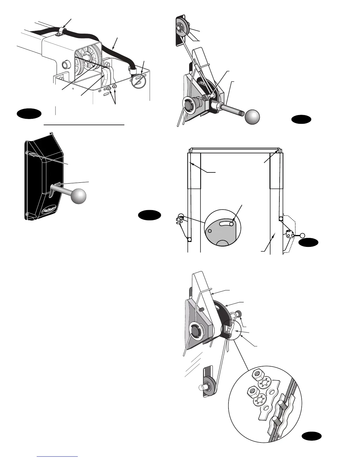
Latch Dog
Shoulder Screw
Control Plate
Cable Clamp
Feed cable up through Cable
Clamp, loop over end of
shoulder bolt and feed back
down through Cable Clamp.
Overhead Hose
#12 Type B x 1/2" Hex
Washer Head Screws
Latch Cable
Latch Cable Guide
The left hole and slot is used
for the SPOA7/SPOA9. The right
hole and slot is used for the SPO9.
Do NOT use
these holes
for Guide.
12. Locking Latch Cable
A) Slip loop end of cable over end of shoulder screw on
right side latch control plate, Fig. 11.
B) Feed the other end of the cable through the latch
cable sheave slot making sure that the cable is
running under the bottom side of the latch cable
sheave and inside the right column, Fig. 11.
C) Route cable up inside column and through the latch
cable guide, Fig. 12 & Fig. 10b.
D) Continue routing cable to the left column latch cable
guide, Fig. 12 & Fig. 10b, routing the cable through
the top of the left column latch cable guide, Fig. 10b.
E) Bring the cable down inside the left column and feed
the end of the cable through the latch cable sheave
slot so that the cable is now back outside the column,
Fig. 13.
F) Route cable under the bottom side of the latch cable
sheave, Fig. 13.
G) At this point you MUST install the latch handle, jam
nut, and right column latch cover Fig. 10c & Fig. 11.
Install latch handle ball, Fig. 11.
H) Insert cable in cable clamp along one side, loop
around shoulder screw and back down, inserting
cable along other side of cable clamp, Fig. 13. Place
top back on clamp, barely tightening.
I) Next, pull the control plate down, Fig. 13, to
eliminate any clearance between the control plate slot
and the latch dog pin, Fig. 12.
J) Using Pliers, pull cable tight and secure the clamp
close to the shoulder screw. Tighten clamp.
Fig. 10c
Fig. 11
(2) 3/8" Retaining Rings
Latch Cable Sheave
Shoulder Bolt
Install Latch Handle using
a 1/2" hex jamb nut to lock in place.
Then install cover and handle ball.
Latch Cable Guide
Right Column
Latch Cable
Notice the clearance
removed between
Control Plate Slot
and Latch Dog Pin.
Fig. 13
Fig. 12
5/16-18NC x 3/8" lg. PHMS
Latch handle MUST be
positioned at the top of
the latch control cover.
Fig. 10b

 Loading...


