7
Hose(outside of column)
Hose Slot
Hose Clip
Sheave Cover
Upper Cable Tie Off
& 1/2" Nylon Insert
Locknut
Lower Cable Tie Off
& 1/2" Nylon Insert
Locknut
To set up cables for a
narrow bay(NB) or a low
ceiling(LC), use 1/2" ID
SCH 40 steel pipe spacers
(not included) at the lower
cable tie off. The lengths
required are as follows:
SPOA7
-NB or LC = 8" (203mm)
-NB & LC = 16" (406mm)
SPOA9
-LC = 8" (203mm)
1/2"(12.7mm) I.D.
SCHEDULE 40
steel pipe spacer
for Narrow Bay
and/or Low Ceiling
1st Cable
2nd Cable
Upper Sheaves
Lower Sheaves
Fig. 10a
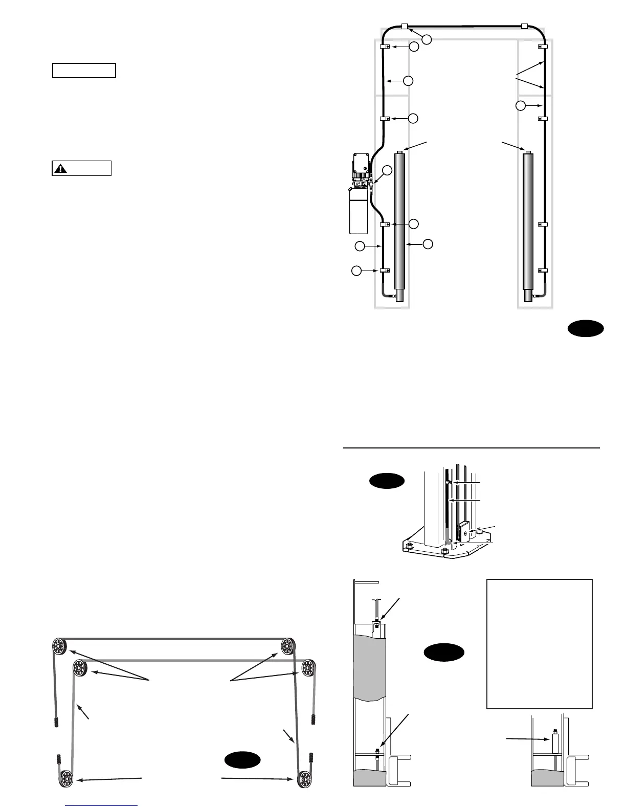
Fig. 9a
ITEM QTY. DESCRIPTION
1 2 Hydraulic Cylinder
2 1 Power Unit Hose
3 1 Overhead Hose
4 1 Branch Tee
5 6 Hose Clips
5 6 5/16-18NC x 3/8 lg. PHMS
6 4 Hose Clips
6 4 #12 Type B x 1/2 lg. Hex
Washer Head Screw
Fig. 9b
Fig. 9c
1
2
6
4
6
FRONT
Hose runs down
approach side to
cylinder on left column.
Cylinder bleeders
5
5
3
3
5
Flared Fittings Tightening Procedure
1. Screw the fittings together finger tight. Then, using the
proper size wrench, rotate the fitting 2-1/2 hex flats.
IMPORTANT
Flare seat MUST NOT rotate when
tightening. Only the nut should turn.
2. Back the fitting off one full turn.
3. Again tighten the fittings finger tight; then using a
wrench, rotate the fitting 2-1/2 hex flats. This will
complete the tightening procedure and develop a
pressure tight seal.
CAUTION
Overtightening will damage fitting resulting
in fluid leakage.
Adapter & Hose Installation (see Fig. 9b)
1. Install Pc. (2) with hose clamps, on power unit column
side connecting it to the cylinder (1) first.
2. Install Pc. (3) with hose clamps starting at left column
cylinder (5) and working toward the right column. All
excess hose should be at bends & inside overhead
assembly.
3. Install Pc. (4) into power unit.
4. Connect Pc. (2) & Pc. (3) to Tee (4).
NOTE: Route Power Unit hose inside columns using
slots provided at column base, Fig. 9c. Route Overhead
Hose in column channel on outside of column, Fig. 9c.
Overhead hose goes over top end of overhead assembly,
Fig. 9b.
11. Equalizing Cables
A) Refer to Fig. 9a for the general cable arrangement.
First, run a cable end up through the small hole in the
lower tie-off plate. Fig. 10a.
B) Push the cable up until the stud is out of the carriage
top opening.
C) Run a nylon insert locknut onto the cable stud so 1/2"
(13mm) of the stud extends out of the locknut.
D) Pull the cable back down, Fig. 10a.
E) Run cable around the lower sheave, then up and
around overhead sheave and across and down to the
opposite carriage, Fig. 9a. Install sheave cover, Fig. 9c.
F) Fasten the cable end to the carriage upper tie-off
bracket. Tighten the locknut enough to apply light
tension to the cable.
G) Repeat procedure for the second cable. Complete lift
assembly. Adjust the tension of both cables during the
final adjustments in Paragraph 21.

 Loading...


