RLD | 3.0/4.01 18
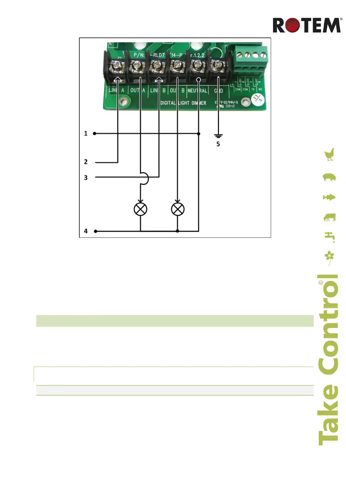
Figure 5: RLD 230V Two Phase Wiring
Key:
1: Neutral
2: 230 VAC Phase A
3: 230 VAC Phase B
4: Neutral
5: Safety ground
)
6.2 Configuring the Channel Levels
The following sections detail how to configure the channel levels.
• Using an Analog Output Card, page 18
• Using a Communication Card, page 20
6.2.1 Using an Analog Output Card
NOTE: Verify that parameter "ch" is set to "0" (refer to System Parameter 2 – Channel, page 10).
1. Connect the 0 – 10 VDC (+) and COM (–) wires from the external device to terminal ports "0-10V
A", "0-10V B" and COM (Figure 5 and Figure 6).
 Loading...