Home
Rotenso
Air Conditioner
LCAC Series
Rotenso LCAC Series Service Manual
5
of 1
of 1 rating
552 pages
Give review
Manual
Specs
To Next Page
To Next Page
To Previous Page
To Previous Page
Loading...
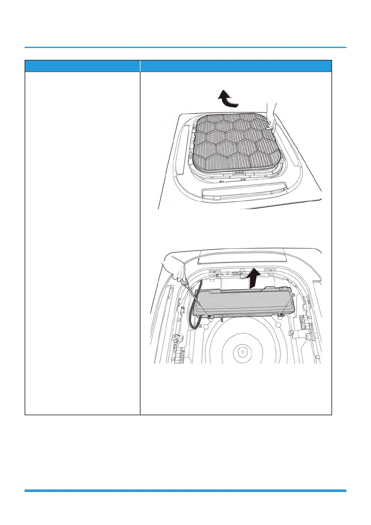
Indoor Unit Disassembly 3
Procedur
e
Illustration
3)
T
urn over the air inlet grille assembly
then pull up the filter
. (see
CJ_
MCD1_003
)
4)
Remove 2 screws and r
emove the
cover of electronic contr
ol box. (see
CJ_MCD1_004
)
CJ_MCD1_003
CJ_MCD1_004
Note: This section is for refer
ence only
. Actual unit appearance may vary
.
448
450
Table of Contents
Section 1
16
Table of Contents
16
Feature
17
Dimensional Drawings
18
Part Names
19
Service Place
19
Accessories
20
Air Velocity and Temperature Distributions
21
Capacity Tables
22
Noise Criterion Curves
28
Electrical Characteristics
29
Electrical Wiring Diagrams
29
Section 2
33
Feature
34
Dimensional Drawings
36
Part Names
37
Service Place
38
Accessories
39
Air Velocity and Temperature Distributions
40
Capacity Tables
48
Noise Criterion Curves
54
Electrical Characteristics
55
Electrical Wiring Diagrams
55
Section 3
63
Feature
64
Dimensional Drawings
66
Part Names
67
Service Place
67
Accessories
68
Air Velocity and Temperature Distributions
69
Capacity Tables
93
Noise Criterion Curves
114
Electrical Characteristics
116
Electrical Wiring Diagrams
117
Section 4
125
Feature
126
Dimensional Drawings
128
Part Names
129
Service Place
129
Accessories
130
Fan Performance
131
Capacity Tables
137
Noise Criterion Curves
164
Electrical Characteristics
167
Electrical Wiring Diagrams
168
Section 5
265
Service Place
276
Capacity Correction Factor for Height Difference
277
Noise Criterion Curves
284
Refrigerant Cycle Diagrams
287
Electrical Wiring Diagrams
290
Section 6
332
First Time Installation Check
333
Refrigerant Recharge
335
Indoor Unit
336
Re-Installation
336
Outdoor Unit
338
Section 7
340
Display Function
341
Safety Features
344
Basic Functions
345
Table
345
Abbreviation
346
Cooling Mode
346
Fan Mode
346
Heating Mode(Heat Pump Units)
347
Auto-Mode
348
Auto-Restart Function
349
Drying Mode
349
Forced Operation Function
349
Sleep Function
349
Timer Function
349
Optional Functions
350
Infrared Wireless Remote Controller
351
Remote Controller Functions
351
LCD Wired Remote Controller
355
Centralized Controller
371
Using the Wire Controller to Set Airflow Rate(for Duct Type)
372
Using the Wire Controller to Set External Static Pressure(for Duct Type)
372
Section 8
373
Safety Caution
375
General Troubleshooting
376
Information Inquiry
378
Error Diagnosis and Troubleshooting Without Error Code
385
Remote Maintenance
385
Field Maintenance
386
Quick Maintenance by Error Code
391
EH 00/EH 0A / EC 51 (EEPROM Parameter Error Diagnosis and Solution)
392
Troubleshooting by Error Code
392
EL 01 (Indoor and Outdoor Unit Communication Error Diagnosis and Solution)
393
EH 03 / EC 07 (Fan Speed Is Operating Outside of the Normal Range )/EC 71(over Current Failure of Outdoor DC Fan Motor) Diagnosis and Solution
395
EH 60/EH 61/EC 53/EC 52/EC 54/EC 56/EC 50 (Open Circuit or Short Circuit of Temperature Sensor Diagnosis and Solution)
399
EL 0C (Refrigerant Leakage Detection Diagnosis and Solution)
400
EH 0E(Water-Level Alarm Malfunction Diagnosis and Solution)
401
PC 00(IPM Malfunction or IGBT Over-Strong Current Protection Diagnosis and Solution)
402
PC 01(over Voltage or too Low Voltage Protection)/Pc
403
Voltage Protection)/Pc 11(Outdoor Unit Main Control Board DC Bus High Voltage
403
PC 03/PC 31(Low Pressure Protection Diagnosis and Solution)
404
PC 04(Inverter Compressor Drive Error Diagnosis and Solution)
404
PC 02(Top Temperature Protection of Compressor or High Temperature Protection of IPM Module Diagnosis and Solution)
406
EC 0D(Outdoor Unit Malfunction Diagnosis and Solution)
407
PC 40(Communication Error between Outdoor Main PCB and IPM Board Diagnosis and Solution)
408
PC 08(Current Overload Protection)/Pc 44(Outdoor Unit Zero Speed Protection)
409
PC 46(Compressor Speed Has Been out of Control)/Pc 49(Compressor Overcurrent Failure) Diagnosis and Solution
409
PC 0F(PFC Module Protection Diagnosis and Solution)
411
EC 72 (Lack Phase Failure of Outdoor DC Fan Motor Diagnosis and Solution)
412
PC 43 (Outdoor Compressor Lack Phase Protection Diagnosis and Solution)
413
PC 0L (Low Ambient Temperature Protection)
414
PC 45 (Outdoor Unit IR Chip Drive Failure Diagnosis and Solution)
414
PC 30 (High Pressure Protection Diagnosis and Solution)
415
PC 0A (High Temperature Protection of Condenser Diagnosis and Solution)
417
PC 06 (Discharge Temperature Protection of Compressor Diagnosis and Solution)
418
Check Procedures
419
Section 9
422
Filter
423
Indoor Unit Disassembly
423
Water Collector
428
Louver Motor of Water Collector
429
Louver Motor of Air Outlet Subassembly
430
Evaporator
432
Section 10
447
Front Panel
448
Indoor Unit Disassembly
448
Display Board
452
Water Pump
454
Water Collector & Water Level Switch
455
Fan Motor and Fan
457
Evaporator
458
Other manuals for Rotenso LCAC Series
User Manual
196 pages
5
Based on 1 rating
Ask a question
Give review
Questions and Answers:
Need help?
Do you have a question about the Rotenso LCAC Series and is the answer not in the manual?
Ask a question
Rotenso LCAC Series Specifications
General
Brand
Rotenso
Model
LCAC Series
Category
Air Conditioner
Language
English
Related product manuals
Rotenso LCAC R32 Series
132 pages
Rotenso TM35X
52 pages
Rotenso MIRAI W
28 pages
Rotenso KASI K26Vi
41 pages
Rotenso KASI K35Vi
41 pages
Rotenso Roni Series
176 pages
Rotenso IMOTO I21Xi
120 pages
Rotenso UKURA W U26W
28 pages
Rotenso UKURA Series
116 pages
Rotenso RONI X Series
64 pages
Rotenso RONI W Series
28 pages
Rotenso IMOTO W Series
28 pages
 Loading...