23
FA ROTEX GW - 09/2012
5 x Start-up
Setting pump speed of heating circulation pump
The prerequisite for the most energy-saving method of operation
is that a hydraulic balance is carried out and the heating circu-
lation pump is running at the lowest possible necessary stage.
The instructions for hydraulic incorporation (see chapter 8) and
the characteristic curves of the residual feed height (chapter 12,
fig. 12-3 and fig. 12-4) must be observed.
Ɣ Fully open all the radiator thermostats / regulating valves.
Ɣ On the ROTEX GW set the highest nominal room temper-
ature so that the burner and the heating circulation pump
operate.
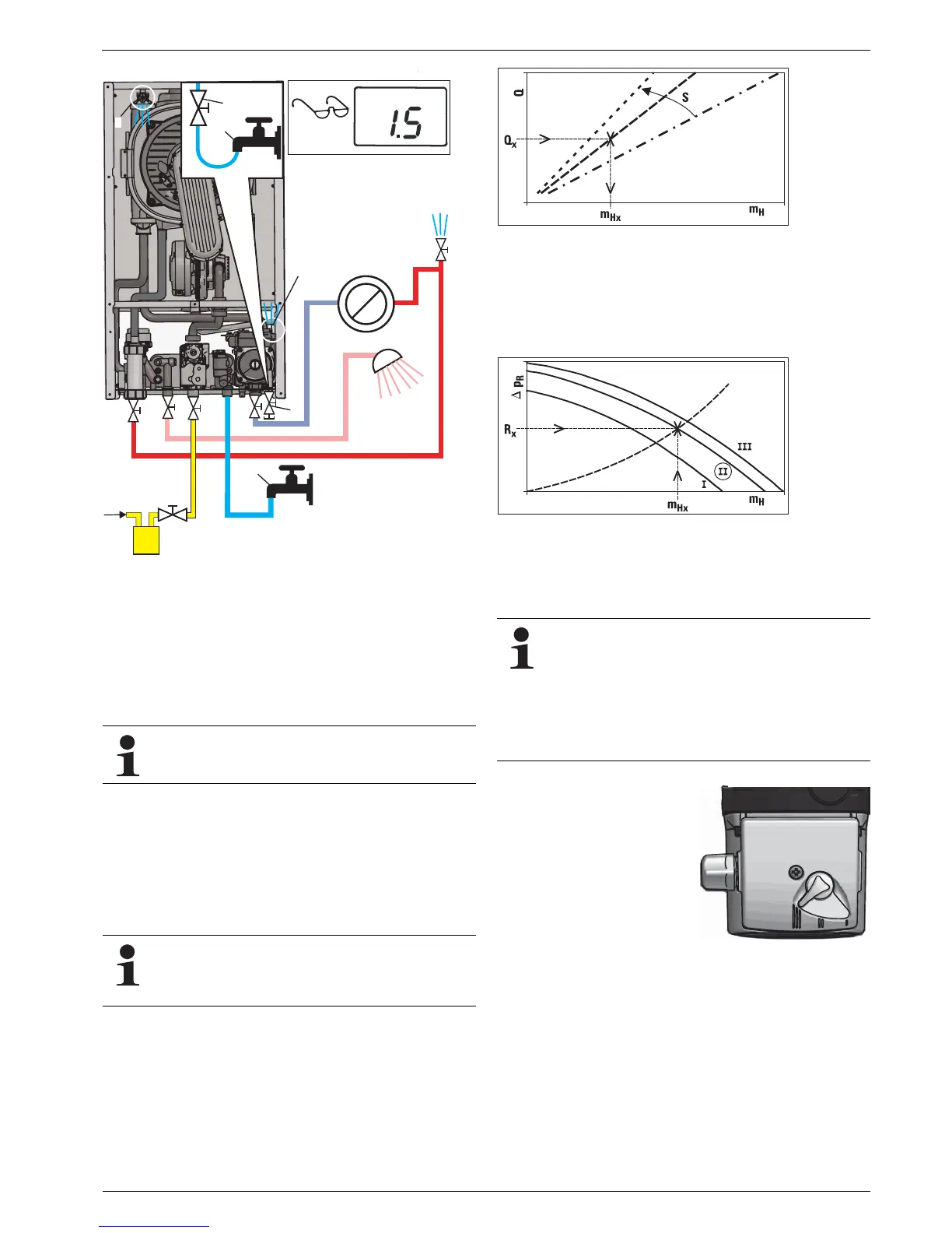
Ɣ In the heating performance diagram (chapter 12 "Technical
data", fig. 12-5) determine the associated flow rate (m
Hx
) for
a specific heating output (Q
x
) depending on the layout
spread.
Ɣ Determine the hydraulic resistance in the heating circuit (R
x
).
Ɣ Based on fig. 12-3 and fig. 12-4 (chapter 12 "Technical data")
determine the output stage of the heating circulation pump.
Fig. 5-2 Filling and bleeding
The pump speed is set in the factory to the highest
pump stage.
The design spread describes the temperature differ-
ence between the flow and return flow of the heating
system under design conditions (generally -12 °C out-
side air temperature).
m
H
Flow heating network Q Heating output
S Spread
Fig. 5-3 Determination of the layout flow rate
m
H
Flow heating network
R
x
Hydraulic resistance in the
heating circuit
'
p
R
Remaining pumping height
I, II, III Pump stages integrated
heating circulation pump
Fig. 5-4 Determination of the required pump output stage
In practice, the hydraulic resistance in the heating net-
work is often not known. By observing the flow and
return flow temperatures on the heat generator, you
can determine whether the pump would still provide
adequate output at a lower speed level.
The difference between the flow and return flow tem-
perature must not be greater than the design spread
and each room must still get warm enough.
Ɣ Setting the heating circu-
lation pump to the required
output stage.
Fig. 5-5 Setting pump speed