7 Installation
Installer reference guide
42
RRLQ004~008CA + RHBH/X04+08CB
ROTEX HPSU low temperature Bi‑bloc
4P384979-1C – 2017.04
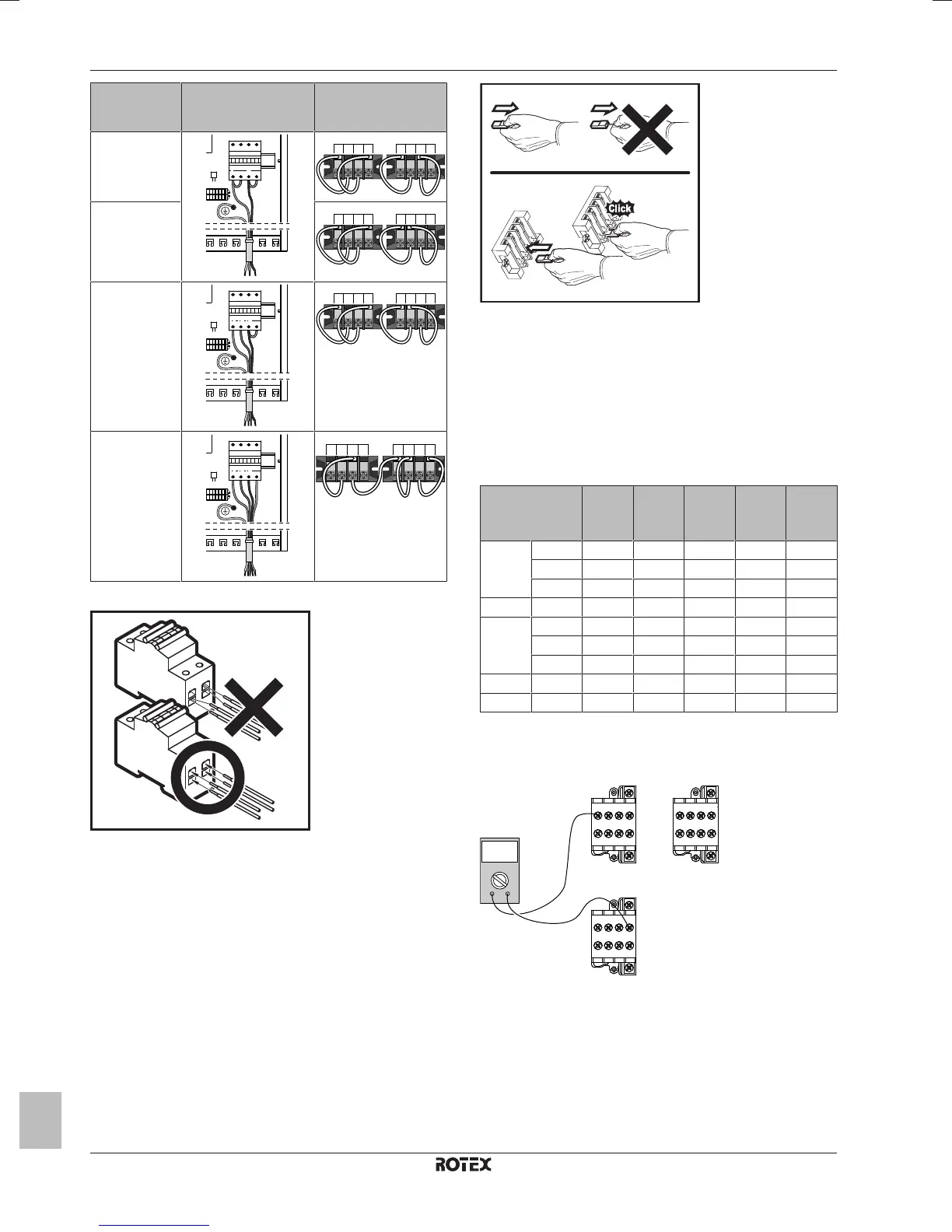
Backup heater
type
Connections to
backup heater power
supply
Connections to
terminals
3kW 1~ 230V
(*9W)
6kW 1~ 230V
(*9W)
6kW 3~ 230V
(*9W)
6kW 3N~ 400V
(*9W)
9kW 3N~ 400V
(*9W)
Special remark for fuses:
Special remark for terminals:
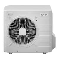
As mentioned on the table above, the connections on the terminals
X6M and X7M need to be changed to configure a backup heater.
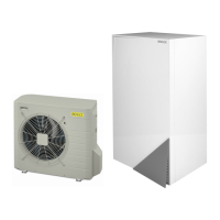
Refer to the illustration below as a caution about handling the
terminals.
3 Fix the cable with cable ties to the cable tie mountings.
4 Configure the user interface for the respective power supply.
See "8.2.2Quick wizard: Standard"on page48.
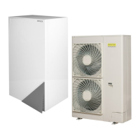
During connection of the backup heater, miswiring is possible. To
detect possible miswiring, it is highly recommended to measure the
resistance value of the heater elements. Depending on the different
backup heater types, following resistance values (see table below)
should be measured. ALWAYS measure the resistance on the
contactor clamps K1M, K2M, and K5M.
3kW
1~
230V
6kW
1~
230V
6kW
3~
230V
6kW
3N~
400V
9kW
3N~
400V
K1M/1 K5M/13 52.9Ω 52.9Ω 52.9Ω ∞ ∞
K1M/3 ∞ ∞ ∞ 105.8Ω 105.8Ω
K1M/5 ∞ ∞ ∞ 105.8Ω 105.8Ω
K1M/3 K1M/5 26.5Ω 26.5Ω 26.5Ω 105.8Ω 105.8Ω
K2M/1 K5M/13 ∞ 26.5Ω 26.5Ω ∞ ∞
K2M/3 ∞ ∞ ∞ 52.9Ω 52.9Ω
K2M/5 ∞ ∞ ∞ 52.9Ω 52.9Ω
K2M/3 K2M/5 52.9Ω 52.9Ω 52.9Ω 52.9Ω 52.9Ω
K1M/5 K2M/1 ∞ ∞ ∞ ∞ ∞
Example measure resistance between K1M/1 and K5M/13:
K1M K2MK2M
1 3 5 13
2 4 6 14
K5M
1 3 5 13
2 4 6 14
1 3 5 13
2 4 6 14
Ω
Ω
7.9.9 To connect the user interface
▪ If you use 1 user interface, you can install it at the indoor unit (for
control close to the indoor unit), or in the room (when used as
room thermostat).
▪ If you use 2 user interfaces, you can install 1 user interface at the
indoor unit (for control close to the indoor unit) + 1 user interface
in the room (used as room thermostat).