7 Installation
Installer reference guide
44
RRLQ004~008CA + RHBH/X04+08CB
ROTEX HPSU low temperature Bi‑bloc
4P384979-1C – 2017.04
2 Fix the cable with cable ties to the cable tie mountings.
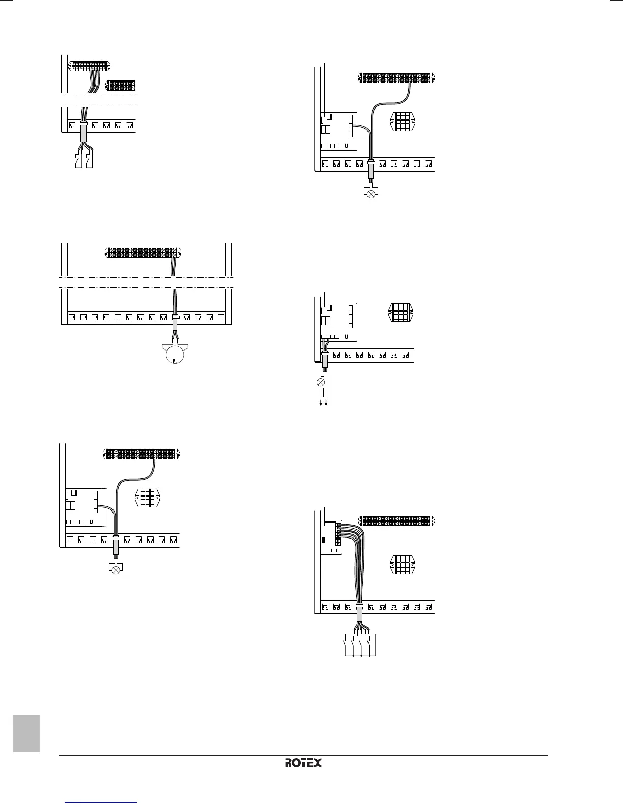
7.9.12 To connect the domestic hot water pump
1 Connect the domestic hot water pump cable to the appropriate
terminals as shown in the illustration below.
2 Fix the cable with cable ties to the cable tie mountings.
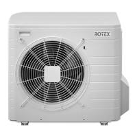
7.9.13 To connect the alarm output
1 Connect the alarm output cable to the appropriate terminals as
shown in the illustration below.
X1M
X2M
29
X1M
YC Y1 Y2 Y3 Y4
A4P
X2M
a
a Installation of EKRP1HB is required.
2 Fix the cable with cable ties to the cable tie mountings.
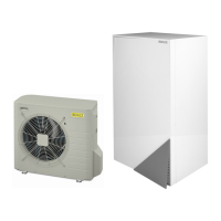
7.9.14 To connect the space cooling/heating ON/
OFF output
1 Connect the space cooling/heating ON/OFF output cable to the
appropriate terminals as shown in the illustration below.
X1M
X2M
29
X1M
YC Y1 Y2 Y3 Y4
A4P
X2M
a
a Installation of EKRP1HB is required.
2 Fix the cable with cable ties to the cable tie mountings.
7.9.15 To connect the changeover to external
heat source
1 Connect the changeover to external heat source cable to the
appropriate terminals as shown in the illustration below.
X1M
X1M
X3 X4
A4P
L N
X2M
X1 X2
a
a Installation of EKRP1HB is required.
2 Fix the cable with cable ties to the cable tie mountings.
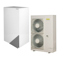
7.9.16 To connect the power consumption digital
inputs
1 Connect the power consumption digital inputs cable to the
appropriate terminals as shown in the illustration below.
X1M
X2M
1 2 3 4 5
A8P
X801M
S6S
S7S
S8S
S9S
a
a Installation of EKRP1AHTA is required.
2 Fix the cable with cable ties to the cable tie mountings.
7.9.17 To connect the safety thermostat (normal
closed contact)
1 Connect the safety thermostat (normal closed) cable to the
appropriate terminals as shown in the illustration below.