14 Technical data
Installer reference guide
87
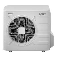
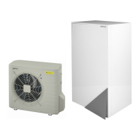
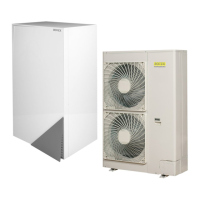
RRLQ004~008CA + RHBH/X04+08CB
ROTEX HPSU low temperature Bi‑bloc
4P384979-1C – 2017.04
English Translation
Remote user interface Remote user interface
Ext. indoor thermistor External indoor thermistor
Ext outdoor thermistor External outdoor thermistor
Digital I/O PCB Digital I/O PCB
Demand PCB Demand PCB
Solar pump and control station Solar pump and control station
Main LWT Main leaving water temperature
On/OFF thermostat (wired) On/OFF thermostat (wired)
On/OFF thermostat (wireless) On/OFF thermostat (wireless)
Ext. thermistor External thermistor
Heat pump convector Heat pump convector
Add LWT Additional leaving water
temperature
On/OFF thermostat (wired) On/OFF thermostat (wired)
On/OFF thermostat (wireless) On/OFF thermostat (wireless)
Ext. thermistor External thermistor
Heat pump convector Heat pump convector
Position in switch box
English Translation
Position in switch box Position in switch box
Legend
A1P Main PCB
A2P User interface PCB
A3P * Solar pump station PCB
A3P * On/OFF thermostat (PC=power circuit)
A3P * Heat pump convector
A4P * Digital I/O PCB
A4P * Receiver PCB (Wireless On/OFF
thermostat)
A5P Anode driver PCB
A8P * Demand PCB
B1L Flow sensor
BSK (A3P) * Solar pump station relay
DS1 (A8P) * DIP switch
E1A Electrical anode
E1H Backup heater element (1kW)
E2H Backup heater element (2kW)
E3H Backup heater element (3kW)
E4H * Booster heater (3kW)
F1B Overcurrent fuse backup heater
F2B * Overcurrent fuse booster heater
F1T Thermal fuse backup heater
F1U, F2U (A4P) * Fuse 5A 250V for digital I/O PCB
FU1 (A1P) Fuse T 6.3A 250V for PCB
K1M, K2M Contactor backup heater
K3M * Contactor booster heater
K5M Safety contactor backup heater (only for
*9W)
K*R (A1P, A4P) Relay on PCB
M1P Main supply pump
M2P # Domestic hot water pump
M2S # 2-way valve for cooling mode
M3S (*) 3-way valve for floor heating/domestic hot
water
PC (A4P) Power circuit
PHC1 (A4P) * Optocoupler input circuit
Q*DI # Earth leakage circuit breaker
Q1L Thermal protector backup heater
Q2L * Thermal protector booster heater
R1H (A3P) * Humidity sensor
R1T (A1P) Outlet water heat exchanger thermistor
R1T (A2P) Ambient sensor user interface
R1T (A3P) * Ambient sensor On/OFF thermostat
R2T (A1P) Outlet backup heater thermistor
R2T (A3P) * External sensor (floor or ambient)
R3T Refrigerant liquid side thermistor
R4T Inlet water thermistor
R5T (*) Domestic hot water thermistor
R6T * External indoor or outdoor ambient
thermistor
S1S # Preferential kWh rate power supply contact
S2S # Electrical meter pulse input 1
S3S # Electrical meter pulse input 2
S4S # Safety thermostat
S6S~S9S # Digital power limitation inputs
SS1 (A4P) * Selector switch
TR1 Power supply transformer
CN1-2, X*A
X1H, X*Y
Connector
X*M Terminal strip
*: Optional
(*): Optional for RHBH/X
#: Field supply
Colours
BLK Black
BRN Brown
GRY Grey
RED Red
Translation of text on wiring diagram
English Translation
(1) Main power connection (1) Main power connection
For preferential kWh rate power
supply
For preferential kWh rate power
supply
Indoor unit supplied from outdoor Indoor unit supplied from outdoor
Normal kWh rate power supply Normal kWh rate power supply
Only for normal power supply
(standard)
Only for normal power supply
(standard)
Only for preferential kWh rate
power supply (outdoor)
Only for preferential kWh rate
power supply (outdoor)
Outdoor unit Outdoor unit
Preferential kWh rate power
supply contact: 16 V DC
detection (voltage supplied by
PCB)
Preferential kWh rate power
supply contact: 16VDC
detection (voltage supplied by
PCB)
Use normal kWh rate power
supply for indoor unit
Use normal kWh rate power
supply for indoor unit
(2) Backup heater power supply (2) Backup heater power supply
Only for *** Only for ***