User Manual - 25/32
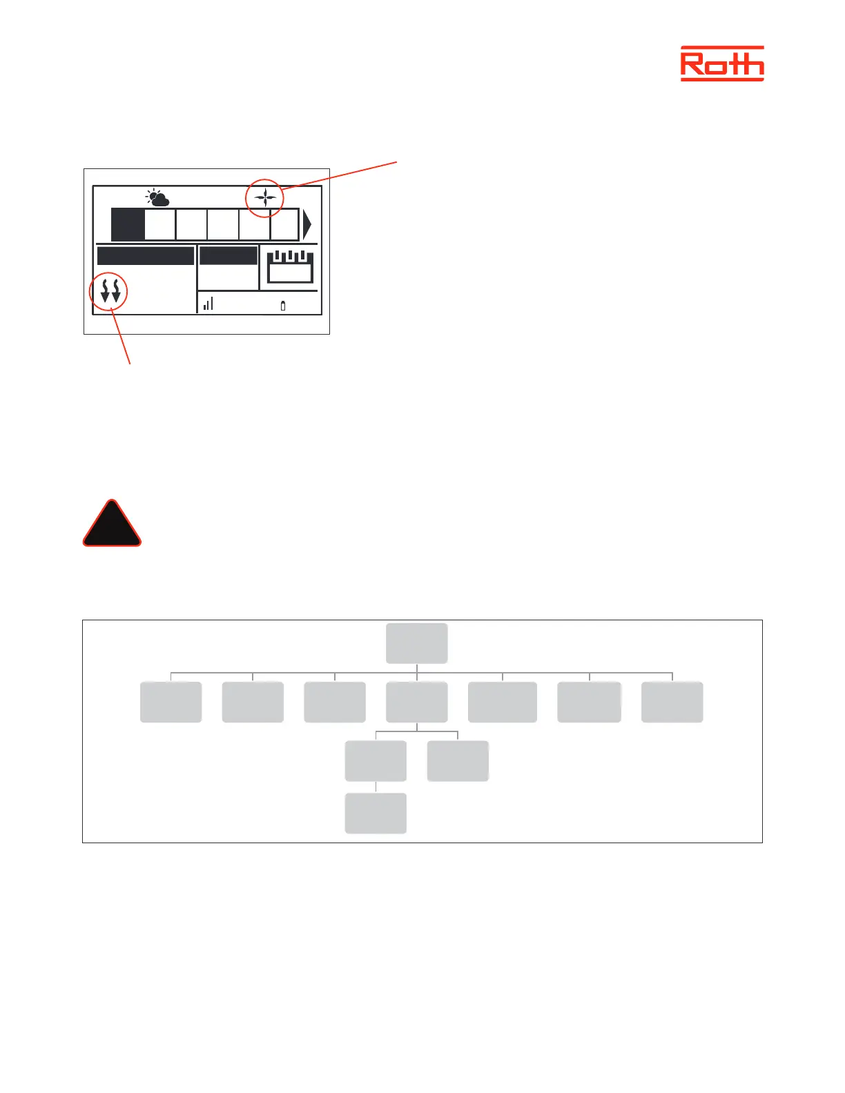
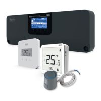
View in display during cooling operation
1. The arrows point downwards, which means that it is cooling.
2. A fan is displayed when cooling
If the maximum humidity is exceeded in a zone, the symbol 1. will switch o, but the
symbol 2. will still be on.
9. MIXING VALVE
The master controller may control additional valve with the use of a Roth Touchline® SL Valve module. The device oers a range of parameters to
adjust the valve operation to individual needs, and also includes the possibility to run the system based on outdoor compensation.
The Roth Touchline® SL Valve module must be connected to the master controller with the RS cable. Please see the specic manual for the Roth
Touchline® SL Valve module.
NOTE
This type of control is available only aer purchasing and connecting the additional Roth Touchline® SL Valve module, which
is not included in the controller delivery.
XII. SERVICE MENU
Diagram - Service menu
Service menu should only be used by a highly qualied person and only when it is necessary to adjust advanced settings that can have a big
inuence on the functionality and performance of the system.
Therefore the access to this MENU is also secured with a password code which is: 1234
To enter menu choose “Service menu” in the main menu – pres MENU button. Enter password by using ▼ or ▲ – press MENU to go to the next
number. Finally conrm by pressing MENU. Due to security reasons you will be automaticly thrown out of the service menu aer 1 minute.
!
Service
menu
Output type Relay delay
Antifreeze
protection
Zones
Floor
heating
Hysteresis
Hysteresis
Max
temperature
Min
temperature
Factory
settings
22.3°
21.0°
13:51
CON
100% 65%
TEMPERATURE SET
Mo.
1 2 3 4 5 6
27.5°C
2
1