4/10
5. Pump and boiler wiring diagrams, for the 24v
Touchline controller.
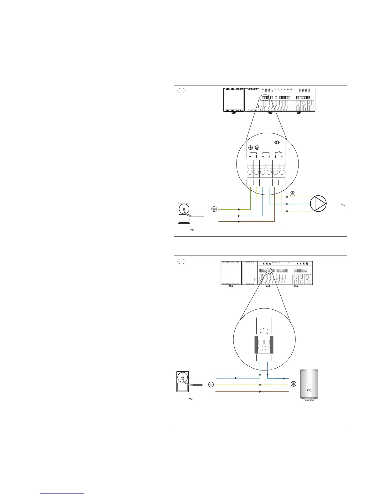
Image 5.a Pump connection diagram
Main, 230V Input on terminals 1, 3, 5 and Pump output
supply from terminals 2, 4, 6 on the Touchline controller.
(Functioning as an On/O switch when heating is required
from the Touchline thermostat).
Image 5.b Boiler connection diagram
Main, 230V Input blue wire on terminal 7, and Boiler
output supply blue wire from terminal 8, on the Touchline
controller.
(Functioning as an On/O switch when heating is required
from the boiler).
NB! If 230V is added on terminal 7 and 8, brown and blue
wire, this will enable cooling mode and the Touchline system
will operate in reversed actuator mode. This is only recom-
mended if the system is designed for cooling not as an boiler
On/O switch.
For the boiler to start when heating is required, please
check the setting in service menu P-51 on a random
Touchline thermostat and set it to setting (1).
To do so please follow the steps below.
1. Enter the thermostat menu by pressing the menu tab
and holding it down, P-01 will show on the display.
2. Use the menu tab again, and go to menu P-SE, Enter by
pressing the (OK) check mark tab.
3. Service menu code is now needed, use the arrow up tab
to set the code 1-2-3-4, Enter by pressing the (OK) check
mark tab.
4. Menu P-20 is now shown, use the thermostat menu tab,
and go to menu P-50, Enter by pressing the (OK) check
mark tab.
5. Menu P-51 is now shown, Enter by pressing the (OK)
check mark tab.
6. Default setting (0) is now shown, Use the arrow up
tab to set the setting up to (1) Enter by pressing the
(OK) check mark tab.
7. Setting is now saved, use the (X) back tab to return to
main display view on the Touchline thermostat.
The boiler will start right away if heating is required.
Don’t forget to activate the 24v actuator thermo element
properly, aer all terminal and thermostat connections are
done.
This is done by setting all thermostats up to 30 degrees
Celsius for 6 - 8 minutes.
When the setting is done and thermostat temperature is set
down again, the 24v actuators will fully close down and the
blue line on the top will disappear.
07
08
N
L
Power outlet
230 volt
c/o out
Boiler
230 volt
N
L
230V
5b
03
01
02
04 05 06
N LLN
N
Pump230V
L
N
L
Power outlet
230 volt
Pump
230 volt
Input
Output
5a