Operating Instructions 5-2 SG8 Manual
Utilize the grooves in the table to align the trunion supports square to the machine.
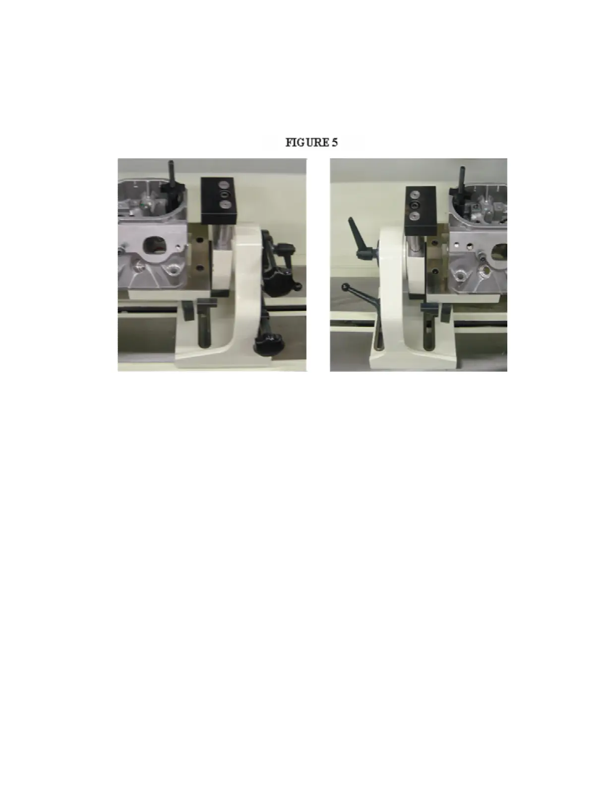
The Rottler-Klamp head mounting fixture is provided to accommodate cylinder heads that are difficult to mount
directly into the trunions. Some machine operators prefer to use the Rottler-Klamp fixture for the majority of heads
as the mounting is very quick. The Rottler-Klamp frame is mounted between the trunions and clamped using the
clamping plates. (Figure 5) The cylinder head is then held to the frame with the swivel clamp assemblies through the
appropriate head bolt holes.
Alignment and Setup:
Alignment and setup applies to both the cylinder head and the machine’s floating head. The goal is to
perfectly align the spindle centerline to the centerline of the area of the head to be machined. Most machining
operations on cylinder heads use the valve guide centerline as the reference point so we will use that as an example.
Note: think of the digital electronic level as a comparator. Because the leveling pin is square to the
machines spindle, as long as you achieve the same readings front to rear and side to side then the spindle will be in
perfect alignment.
Front to Rear Cylinder Head Alignment:
Position the level on level pin to read front to rear and take a reading. Rotate the cylinder head so that the
valve seats are facing up. Now place the level on a pilot in the cylinder head and position the level to read front to rear.
Loosen the lock levers on the supports. Be certain the fine adjustment lock screw is loosened. Coarse adjustment
is made by turning the work piece manually, until the level reading is within a couple of degrees of the reading on the
leveling post.
Lightly tighten the lock levers on the supports to remove any play. Now tighten the clamp on the fine
adjustment screw. Turn the adjustment knob to achieve the exact reading that was observed on the leveling
post. You can now completely tighten both the left and right support locks.
Note: An optional alignment bar is available that helps establish the front to back alignment on canted
valve cylinder heads. The bar is held against two pilots in two adjacent guides. Use the alignment post to adjust
the angle.
Left to Right Alignment:
Obtain the left to right reading from a pilot mounted in a guide in the cylinder head. Now place the level on the leveling
post . Loosen both of the tilt lock levers on each side of the quill housing. Use the tilt adjusting hand wheel to
adjust the reading to be the same as that found on the pilot in the cylinder head. Tighten the tilt lock levers.