Operating Instructions 5-3 SG8 Manual
Selecting the right Pilot:
IMPORTANT: the pilot is the only link between one fixed part - the clamped cylinder head and pilot and a
moving and heavy part, the workhead.
The centering accuracy and the machining accuracy depend on the carbide pilot you select.
Choosing the right pilot will ensure the accuracy of the machining.
The pilot is selected according to the actual guide and not according to the original guide diameter or the
valve stem diameter.
Three Angle Seat Cutting:
Place the ball drive adapter in the spindle.
Align spindle to valve guide.
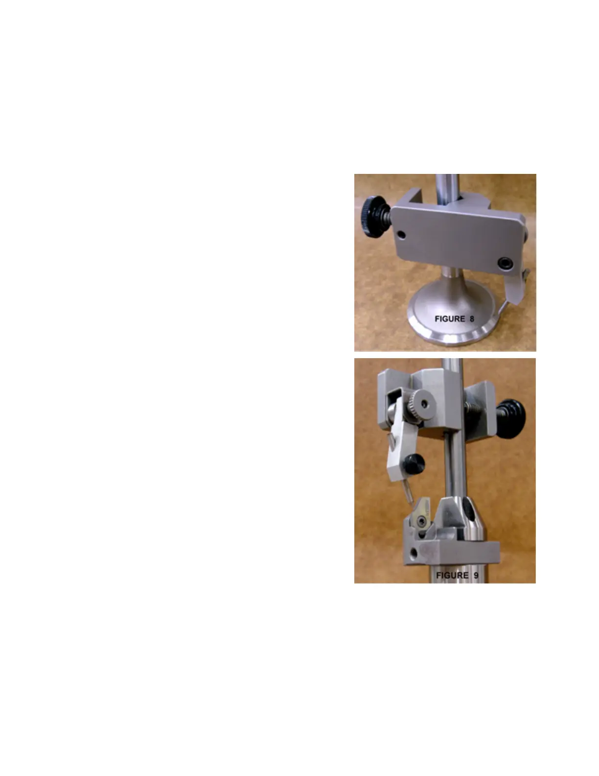
Place a valve in the setting fixture. Position the pointer on the
valve where you wish to place the top of the seat.
Remove the valve; replace it with the correct pilot.
Select the proper diameter tool holder. Place the carbide insert
in tool holder. Slide tool holder onto ball head.
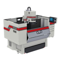
Place ball head over the pilot in setting fixture. Use radial
adjusting screw to set diameter of cutter to correspond to
position of pointer on setting fixture. Tighten hex socket screws
on bottom of ball head. See figure 9
Remove ball head assembly from setting fixture. Place fixed
carbide pilot in cylinder head.
Center the spherical ball head toolholder over the pilot shank.
Required spindle rotation speed will vary, depending on seat
hardness. As seat hardness increases, so does the required spindle
speed. Some will require full speed.
Special care should be taken in centering the floating head
above the valve guide, to achieve a concentric seat.
Cut seat only enough to clean up surface.
Too much cutting will sink the valve too far in the head. Many
operators prefer to use the spindle fine feed when machining
seats as extreme control of spindle down feed can be
accomplished.
Changing the Spindle Adapters:
Once that you have the toolholder setup, fit the ball head toolholder into the spring free spindle adapter.
The SG8 spindle was engineered to allow ultra fast tooling changes .Make sure the that spindle spring free
locking nut is in the off lock position, line up the two ears of the spindle adapter and insert into the spindle
ISO 30 taper, the locking nut automatically will be on the lock position, to remove turn the self locking nut to
the left position, hold the spindle adapter, it may drop on the machine table. Damage will result.
Installing the Spherical self Aligning toolholder:
Once the spring free adapter is in the spindle, fit the Rottler Spherical Self aligning Toolholder
assembly into
the spindle adapter; make sure to align the locator pins before you fit it into the spindle adapter and push it
until you feel that is lock.