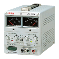
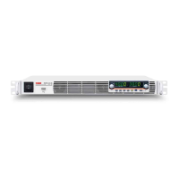
3-1 Front panel (See Fig. 3-1)
(1) CV Indicator lights when the power is on and this unit is in constant voltage operation.
(2) CC Indicator lights when this unit is in constant current operation.
(3) Voltage coarse for the coarse adjustment of the output voltage.
(4) Voltage fine for the fine adjustment of the output voltage.
(5) Current coarse for the coarse adjustment of the output current.
(6) Current fine for the fine adjustment of the output current.
(7) “+” output terminal positive polarity (Red).
(8) “GND” terminal earth and chassis ground (Green).
(9)
“–” output terminal
negative polarity (Black).
(10) meter indicates the output voltage (Analog type).
(11) meter indicates the output current (Analog type).
(12) A/V selects switch selects whether he meter indicates the output voltage or current.
(13) Power control on/off switch.
(14) Current HI/LO control current indicates HI/LO range SELECTS.
3-2 Rear panel (See Fig. 3-2)
(15) Fuse holder
(16) Power cord
(17) AC selects switch With (18) switch selects the line voltage at the high end (right position) of the
range 120V or 230V and at the low end (left position) of the range 100V or 220V.
(18) AC selects switch Selects the line voltage is in the 100V-120V range (left position) or in the
220V-230V in the range (right position).
(19) Master-Slave switch Selects for Master (internal control) or Slave (external remote control) tracking
operation.
(20) Input-Output connector With (19) Master-Slave switch selects, permit from the Master unit (SER. or
PAR.) output connected to Slave unit (SER. or PAR.) inputs.