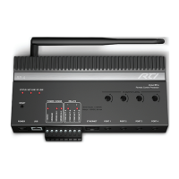
Remote Control Processor
XP-3
16
CHAPTER 3 | INSTALLATION AND OPERATION
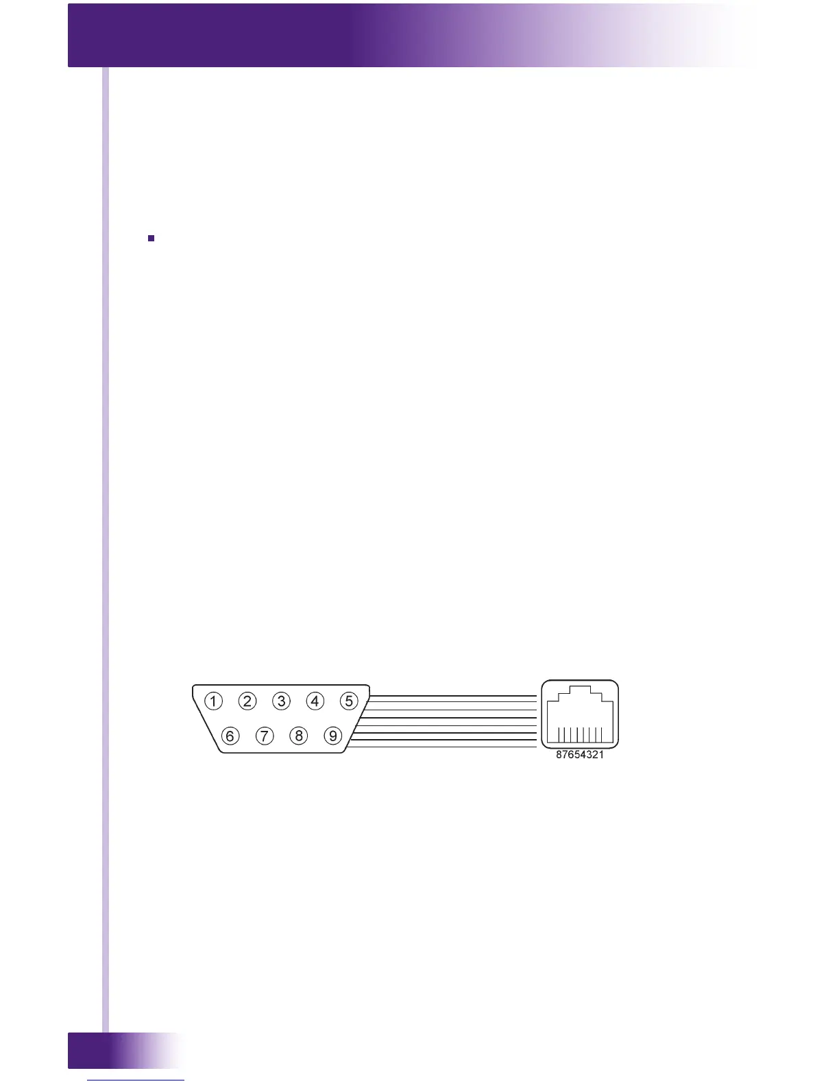
DB-9 Connector Pin Out
Pin Signal Signal
Name Description
1 DCD Carrier Detect
2 RXD Receive Data
3 TXD Transmit Data
4 DTR Data Terminal Ready
5 GND Signal Ground/Common
6 DSR Data Set Ready
7 RTS Request To Send
8 CTS Clear To Send
9 NC Not Connected
RJ-45 Connector Pin Out
Pin Signal Signal
Name Description
1 DSR Data Set Ready
2 DCD Carrier Detect
3 DTR Data Terminal Ready
4 GND Signal Ground/Common
5 RXD Receive Data
6 TXD Transmit Data
7 CTS Clear To Send
8 RTS Request To Send
RJ-45 TO DB-9 ADAPTER PINOUT
RELAYS
The two relays in the XP-3 can provide contact closure or switching control
for loads up to 5A/30VDC each. Both relays are Normally Open when not
energized, but they can be programmed to behave Normally Closed as long
as power is applied to the XP-3.
For contact closure control, connect the A and B contact terminals of a
relay to the desired device.
ETHERNET
This RJ-45 port allows connection to a 10/100 Base-T Ethernet network
(LAN) for programming, control and two-way communication with
compatible devices. Network settings such as the IP address are
congurable within Integration Designer. This port also supports Power-
over-Ethernet (POE) which will power the XP-3 (see powering section).
USB PORT
Used to download the Integration Designer programming software or
rmware into the XP-3.
RS-232 PORT
The XP-3 is capable of two-way RS-232 communication and uses industry
standard cat5 cable with RJ-45 termination (EAI-561).
NOTE: RS-232 communication is limited to 50 feet depending on the baud
rate.