Remote Control Processor
XP-3
14
CHAPTER 3 | INSTALLATION AND OPERATION
POWER
The included AC adapter should be connected to the POWER jack on the
XP-3 or the 12VDC/Ground terminals (see below). The power LED will turn-
on. Use only the supplied AC adapter to power the XP-3. Using a different
power adapter could result in damage to the XP-3 or poor performance.
ALTERNATIVE POWERING METHOD: POWER-OVER-ETHERNET
(POE)
The XP-3 can alternatively be powered using Power-Over-Ethernet,
allowing the power to be extended to the XP-3 over the same cat-5 cable
that carries Ethernet communication. If this method will be used, a class 3
POE router or POE injector will need to be used.
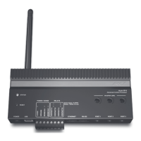
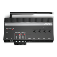
CONNECTION OF RTI RM-433 ANTENNA
Connect an RTI RM-433 to the +12VDC, GROUND, and SENSE IN 1
terminals. The SENSE IN 1 input must be congured as an RTI trigger
input using RTI’s Integration Designer software. (see Connection Options
diagrams for more information).
CONNECTION OF RTI KEYPAD
Connect an RTI in-wall keypad IR output to the GROUND and SENSE IN
1 terminals. The SENSE IN 1 input must be congured as an RTI trigger
input using RTI’s Integration Designer software. (see Connection Options
diagrams for more information).
NOTE: The RTI in-wall Keypad will need its own power source,
such as a power supply or CB-8 touchpanel connecting block (refer
to the operation guides of these devices for cabling requirements).
The RTI RK3-V in-wall Keypad, however, can be powered from the
same POE switch as the XP-3.
VOLTAGE SENSE INPUTS/RTI TRIGGER INPUT
The XP-3 has two voltage sense inputs (+3-24 VDC) that are congurable
within Integration Designer. During the execution of an event, macros can
trigger IR commands, RS-232 commands, relay closure, etc., based on the
status of the voltage sense input.
Connect positive lead from voltage source to Sense In 1 or 2 terminal
input and negative lead to Ground terminal.
NOTE: The SENSE IN 1 terminal can be congured in Integration
Designer as an input for the RTI RM-433 antenna and RTI in-wall
keypads.
NOTE: When congured as an RTI trigger input, it does not allow
IR pass-through from external devices and does not support IR
receivers.