13
It’s Under Control
®
CHAPTER 3 | INSTALLATION AND OPERATION
MOUNTING
The XP-3 can be wall mounted (details below) or free standing.
The XP-3 does not need to be mounted near the equipment being
controlled. The IR output ports and the optional Power Sensor modules
can be extended up to 1000 feet. If RS-232 control ports or the CM-232
Communication Module are used, the distance limitation is usually 50 feet
depending on baud rate.
MOUNTING INSTRUCTIONS
To mount the XP-3 to a wall, shelf, or cabinet you must use the enclosed
mounting plate.
• Level and anchor XP-3 mounting plate to desired wall, shelf, or cabinet
by screwing appropriate wall, shelf, or cabinet fasteners (not included
with the XP-3) through the mounting plate fastener holes.
• When mounting the XP-3, be certain to choose a safe location (e.g.
away from electrical junction boxes, circuit breakers, wet locations,
etc.)
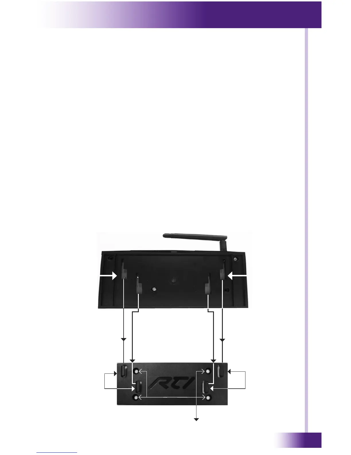
• Afx the XP-3 to the mounting plate by placing the XP-3 channel
locks located on the rear of the XP-3 over the XP-3 channel lock clips
located on the front of the mounting plate. Slide the XP-3 down until
the channel lock clips lock into place.
XP-3 Mounting Plate
Mounting Plate Fastner Holes
XP-3
Channel
Locks
Rear of XP-3
XP-3 Channel
Lock Clips
XP-3 Channel
Lock Clips
XP-3
Channel
Locks