EasyManua.ls Logo

RTK ST 5112-33 User Manual

Default Icon
16 pages
Go to English
To Next Page IconTo Next Page
Page #1 background imageLoading...
Page #1 background image
Einbau- und Betriebsanleitung
Installation and Operating instructions
Instructions de montage et de service
Elektrischer Stellantrieb
Electric Actuator
Servomoteur électrique
5112-8010
Baureihe / Series / Séries
ST 5112
10/2012
Inhaltsverzeichnis
Seite
1 Aufbau auf Armaturen 2
2 Elektrischer Anschluß 2
3 Handbetätigung 2
4 Probelauf 2
5 Einstellung 2
6 Heizung 3
7 Austausch von Bauteilen 4
8 Wartung, Instandhaltung 4
Content
page
1 Fitting onto valves 5
2 Electrical connection 5
3 Manual operation 5
4 Trial operation 5
5 Settings for Actuator 5
6 Heating 6
7 Replacement of components 7
8 Maintenance, repair 7
Index
page
1 Installation sur les vannes 8
2 Connexions électriques 8
3 Commande manuelle 8
4 Contrôle démarrage 8
5 Réglages 8
6 Chauffage 9
7 Remplacement des composants 10
8 Maintenance et entretien 10
Anhang / Appendix/Annexe
1 Technische Daten / Technical data /
Caractéristique techniques 11
2 Elektrischer Anschlußplan / Terminal connection /
schéma de cablage 12
3 Komponenten /components 13
4 Ersatzteilliste / spare parts list / liste de rechange 14
Question and Answer IconNeed help?

Do you have a question about the RTK ST 5112-33 and is the answer not in the manual?

RTK ST 5112-33 Specifications

General IconGeneral
BrandRTK
ModelST 5112-33
CategoryController
LanguageEnglish

Summary

Fitting onto Valves

Electrical Connection

Manual Operation

Trial Operation

Settings for Actuator

Force switch setting

Factory setting of the force switch for closing force. No adjustment is required.

Setting the limit switches

Adjusting spindles E1 and E2 for OPEN and CLOSED travel limits. These are wired with the force switch.

Setting additional limit switches

Using E3 and E4 to signal intermediate positions. Refer to the connection drawing for logic.

Potentiometer adjustment

Adjusting the potentiometer for CLOSED (4mA) and OPEN (20mA) end positions using trimmer T1/T2.

Electronic positioner adjustment

Refer to separate operating instructions for electronic positioner adjustment procedures.

Heating

Replacement of components

Replacement of the motor p.c.b.

Steps to replace the motor printed circuit board, including clutch and cam plate removal.

Motor capacitor replacement

Procedure to replace the motor capacitor, ensuring the actuator is de-energized first.

Replacement of the motor

Steps for replacing the motor, involving disconnecting terminals and re-mounting.

Maintenance, repair

Anhang / Appendix/Annexe

Technische Daten / Technical specification / Caractéristiques techniques

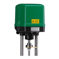
Technical specifications and data for the actuator models ST 5112-32, -33, -34.

Elektrischer Anschlußplan / Terminal connection / schéma de cablage

Wiring diagrams and terminal connections for the ST 5112 actuator.

Komponenten/components

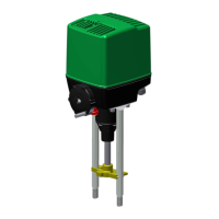
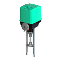
Listing of internal components of the actuator with corresponding figures and part numbers.

Ersatzteilliste / spare parts list / liste de rechange

List of available spare parts for the actuator with order numbers and descriptions.

Related product manuals