23
Installation
1.8 Pour les entrepôts ou les grands ateliers, il peut être
acceptable d'utiliser un nombre réduit de systèmes
de chauffage de plus grande taille.
1. Read and follow the instructions in this manual.
2. Heaters are to be installed and serviced only
by qualified personnel experienced in electrical and
piping work.
3. Installation, piping, and wiring of he heater must
adhere to all applicable codes.
4. It is essential that any unit heater that will be used
in a hazardous (classified) location is equipped with
a electric motor approved for such service, and the
temperature of the heat transfer medium is below
the ignition temperature of the atmosphere.
5. Do not operate heater in atmospheres which are
corrosive to steel or aluminum, unless it has been
coated with a factory approved protective coating.
6. For steam service use only single-pass models.
Refer to model coding (page 7) for number of
passes in heat exchanger.
7. Refer to heat exchanger data plate for pressure
and temperature limits.
8. Heater must be kept clean. When operating in
a dirty environment, regularly clean the finned
tubes, fan and fan guard. Follow the recommended
maintenance procedures. Refer to the “Heater
Maintenance Checklist” section for details.
9. Use factory approved replacement parts only.
10. If there are any questions or concerns regarding
the heater, contact the factory. Refer to the last
page of this manual for details.
WARRANTY W I LL B E V OID
I F INSTR U C TIONS ARE NO T F O L LOW E D
INSTALLATION
The installation instructions provide a general guideline for the installation and wiring of the heater.
All applicable codes must be adhered to.
MECHANICAL
LOCATION
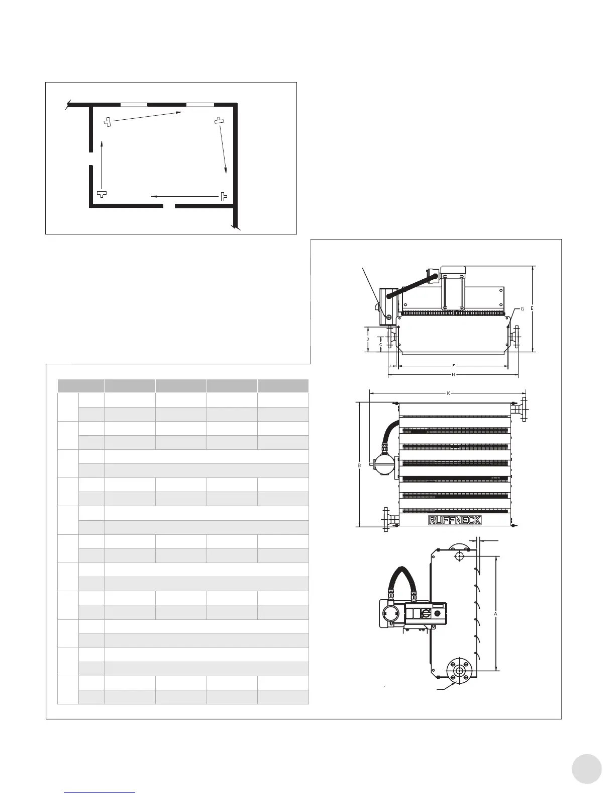
1. For optimum heating, the heaters should be installed as
follows:
a. There are no obstructions that may impede the heater’s
air inlet or discharge.
b. The air discharge is directed into open areas and not at
occupants.
c. The air discharge is not directed at a thermostat.
d. The air discharge is directed across areas of heat loss,
such as doors and windows (see Figure 1).
e. The air discharge is directed along, and at a slight angle
towards, exterior walls (see Figure 1).
f. If equipment freeze protection is important, direct air
discharge at equipment.
g. Air discharge streams support each other and create a
circular air flow. It is not required that the heater’s air
throw reaches the next heater.
h. For warehouses or large workshops it may be
acceptable to use fewer, larger heaters.
- 3 -
FIGURE 1
IMPORTANT NOTICES
WARNING:
Read and adhere to the following. Failure to do so may result in severe or fatal injury.
CLOISON
EXTÉRIEURE
CLOISON EXTÉRIEURE
Figure1
2. Montage
2.1 L'unité de chauffage est conçue pour être installée
en position verticale et à plat. Toutefois, elle peut
être installée dans n'importe quelle position, à
condition que, pour le service vapeur, l'entrée soit
au-dessus de la sortie, et que le fond de l'échangeur
de chaleur se déverse vers la sortie.
2.2 Les armoires des systèmes de chauffage sont
conçues pour être montées depuis le dessus ou
le dessous, à l'aide de boulons de1/2" (14 mm).
Pour les dimensions du système de chauffage,
consultez la section Figure2, page23 ou
Figure3, page24 pour un ventilateur simple ou
pour un tandem de ventilateurs24".
2.3 Le support de montage doit être sufsamment solide
pour:
– Soutenir le poids du système de chauffage (voir la
section E. Caractéristiques, page29),
– Assurer une rigidité sufsante pour éviter les
vibrations excessives et
– Résister à des situations difciles, telles que des
installations transportables.
Figure2
Dim. AH-12A AH-16A AH-20A AH24A
A
po 15-13/16 19-13/16 23-13/16 27-7/8
mm 401 503 605 707
B
po 19-7/16 23-1/2 27-1/2 31-1/2
mm 494 596 698 800
C
po 4-3/16
mm 107
D
po 7-15/16 7-9/16 7-3/16 6-7/8
mm 201 192 183 174
E
po 23-5/8
mm 600
F
po 18-3/16 22-3/16 26-3/16 30-3/16
mm 462 564 665 766
G
po 9/16
mm 14,3
H
po 23-7/8 27-7/8 31-7/8 35-7/8
mm 606,5 708,5 809,5 911,5
I
po 1-9/16
mm 39
J
po 5/8
mm 16
K
po 27-1/2 31-5/8 35-1/2 39-5/8
mm 698,5 802,5 903 1005
FIGURE 3
FIGURE 2
AH-24B Tandem
A
in. 52-15/16
mm 1345
B
in. 31-1/2
mm 800
C
in. 4-13/16
mm 122
D
in. 7-7/16
mm 189
E
in. 24-3/16
mm 615
F
in. 58-1/4
mm 1480
G
in. 9/16
mm 14.3
H
in. 36-7/8
mm 937
I
in. 2-1/16
mm 53
J
in. 5/8
mm 16
K
in. 59-1/2
mm 1512
DIM AH-12A AH-16A AH-20A AH-24A
A
in 15-13/16 19-13/16 23-13/16 27-7/8
mm 401 503 605 707
B
in 19-7/16 23-1/2 27-1/2 31-1/2
mm 494 596 698 800
C
in 4-3/16 4-3/16 4-3/16 4-3/16
mm 107 107 107 107
D
in 7-15/16 7-9/16 7-3/16 6-7/8
mm 201 192 183 174
E
in 23-5/8 23-5/8 23-5/8 23-5/8
mm 600 600 600 600
F
in 18-3/16 22-3/16 26-3/16 30-3/16
mm 462 564 665 766
G
in 9/16 9/16 9/16 9/16
mm 14.3 14.3 14.3 14.3
H
in 23-7/8 27-7/8 31-7/8 35-7/8
mm 606.5 708.5 809.5 911.5
I
in 1-9/16 1-9/16 1-9/16 1-9/16
mm 39 39 39 39
J
in 5/8 5/8 5/8 5/8
mm 16 16 16 16
K
in 27-1/2 31-5/8 35-1/2 39-5/8
mm 698.5 802.5 903 1005
L
in. 65-1/2
mm 1662.5
ENTRÉE D'ALIMENTATION1" NPT
FIGURE 3
FIGURE 2
AH-24B Tandem
A
in. 52-15/16
mm 1345
B
in. 31-1/2
mm 800
C
in. 4-13/16
mm 122
D
in. 7-7/16
mm 189
E
in. 24-3/16
mm 615
F
in. 58-1/4
mm 1480
G
in. 9/16
mm 14.3
H
in. 36-7/8
mm 937
I
in. 2-1/16
mm 53
J
in. 5/8
mm 16
K
in. 59-1/2
mm 1512
DIM AH-12A AH-16A AH-20A AH-24A
A
in 15-13/16 19-13/16 23-13/16 27-7/8
mm 401 503 605 707
B
in 19-7/16 23-1/2 27-1/2 31-1/2
mm 494 596 698 800
C
in 4-3/16 4-3/16 4-3/16 4-3/16
mm 107 107 107 107
D
in 7-15/16 7-9/16 7-3/16 6-7/8
mm 201 192 183 174
E
in 23-5/8 23-5/8 23-5/8 23-5/8
mm 600 600 600 600
F
in 18-3/16 22-3/16 26-3/16 30-3/16
mm 462 564 665 766
G
in 9/16 9/16 9/16 9/16
mm 14.3 14.3 14.3 14.3
H
in 23-7/8 27-7/8 31-7/8 35-7/8
mm 606.5 708.5 809.5 911.5
I
in 1-9/16 1-9/16 1-9/16 1-9/16
mm 39 39 39 39
J
in 5/8 5/8 5/8 5/8
mm 16 16 16 16
K
in 27-1/2 31-5/8 35-1/2 39-5/8
mm 698.5 802.5 903 1005
L
in. 65-1/2
mm 1662.5
(MAX)
Bride2" ou 11/2300#
NPT MÂLE2" or 11/2
 Loading...