5
Installation
2. Mounting
2.1 The unit heater is designed to be installed in an
upright and level position. However, it may be
installed in any position provided that for steam
service the inlet is above the outlet and the bottom
of the heat exchanger drains towards the outlet.
2.2 Heater cabinets are designed to be mounted from
the top or bottom using 1/2" (14mm) bolts. For
heater dimensions, see Figure2, page5 for
single fan or Figure3, page6 for 24" tandem.
2.3 The mounting structure must be strong enough to:
– Support the heater’s weight (refer Section E.
Specications, page11),
– Provide sufcient stiffness to prevent excessive
vibration, and
– Withstand abusive situations such as transportable
installations.
2.4 For ease of installation, a variety of mounting kits are
available from the factory.
3. Mounting Heights
3.1 The base of the heater is to be elevated a minimum
of 7.9ft (2.4m) above the oor.
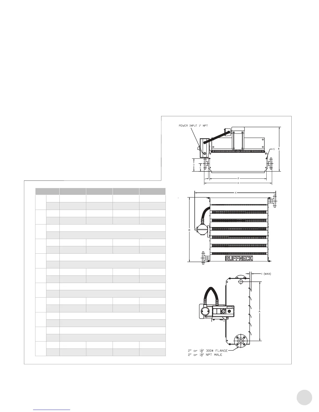
FIGURE 3
FIGURE 2
AH-24B Tandem
A
in. 52-15/16
mm 1345
B
in. 31-1/2
mm 800
C
in. 4-13/16
mm 122
D
in. 7-7/16
mm 189
E
in. 24-3/16
mm 615
F
in. 58-1/4
mm 1480
G
in. 9/16
mm 14.3
H
in. 36-7/8
mm 937
I
in. 2-1/16
mm 53
J
in. 5/8
mm 16
K
in. 59-1/2
mm 1512
DIM AH-12A AH-16A AH-20A AH-24A
A
in 15-13/16 19-13/16 23-13/16 27-7/8
mm 401 503 605 707
B
in 19-7/16 23-1/2 27-1/2 31-1/2
mm 494 596 698 800
C
in 4-3/16 4-3/16 4-3/16 4-3/16
mm 107 107 107 107
D
in 7-15/16 7-9/16 7-3/16 6-7/8
mm 201 192 183 174
E
in 23-5/8 23-5/8 23-5/8 23-5/8
mm 600 600 600 600
F
in 18-3/16 22-3/16 26-3/16 30-3/16
mm 462 564 665 766
G
in 9/16 9/16 9/16 9/16
mm 14.3 14.3 14.3 14.3
H
in 23-7/8 27-7/8 31-7/8 35-7/8
mm 606.5 708.5 809.5 911.5
I
in 1-9/16 1-9/16 1-9/16 1-9/16
mm 39 39 39 39
J
in 5/8 5/8 5/8 5/8
mm 16 16 16 16
K
in 27-1/2 31-5/8 35-1/2 39-5/8
mm 698.5 802.5 903 1005
L
in. 65-1/2
mm 1662.5
Dim. AH-12A AH-16A AH-20A AH24A
A
in 15-13/16 19 13/16 23-13/16 27-7/8
mm 401 503 605 707
B
in 19-7-16 23-1/2 27-1/2 31-1/2
mm 494 596 698 800
C
in 4-3/16
mm 107
D
in 7-15/16 7-9/16 7-3/16 6-7/8
mm 201 192 183 174
E
in 23-5/8
mm 600
F
in 18-3/16 22-3/16 26-3/16 30-3/16
mm 462 564 665 766
G
in 9/16
mm 14.3
H
in 23-7/8 27-7/8 31-7/8 35-7/8
mm 606.5 708.5 809.5 911.5
I
in 1-9/16
mm 39
J
in 5/8
mm 16
K
in 27-1/2 31-5/8 35-1/2 39-5/8
mm 698.5 802.5 903 1005
Figure2
3.2 Heaters maybe mounted at higher elevations and
still provide warm air at the oor level. The maximum
elevation at which warm air will still reach the oor
depends on site and operation conditions.
3.3 Louvers can be adjusted to provide greater
downward deection of the discharge air. It is
recommended that louvers not be closed more than
75° from full open.
4. Mounting Clearances
4.1 Leave at least 20" (500mm) clearance between the
rear of the motor and the nearest obstruction.
4.2 Clearance equal to the height of the heater cabinet
above, or beneath, the cabinet is required for easy
fan or motor replacement.
 Loading...