6
Installation
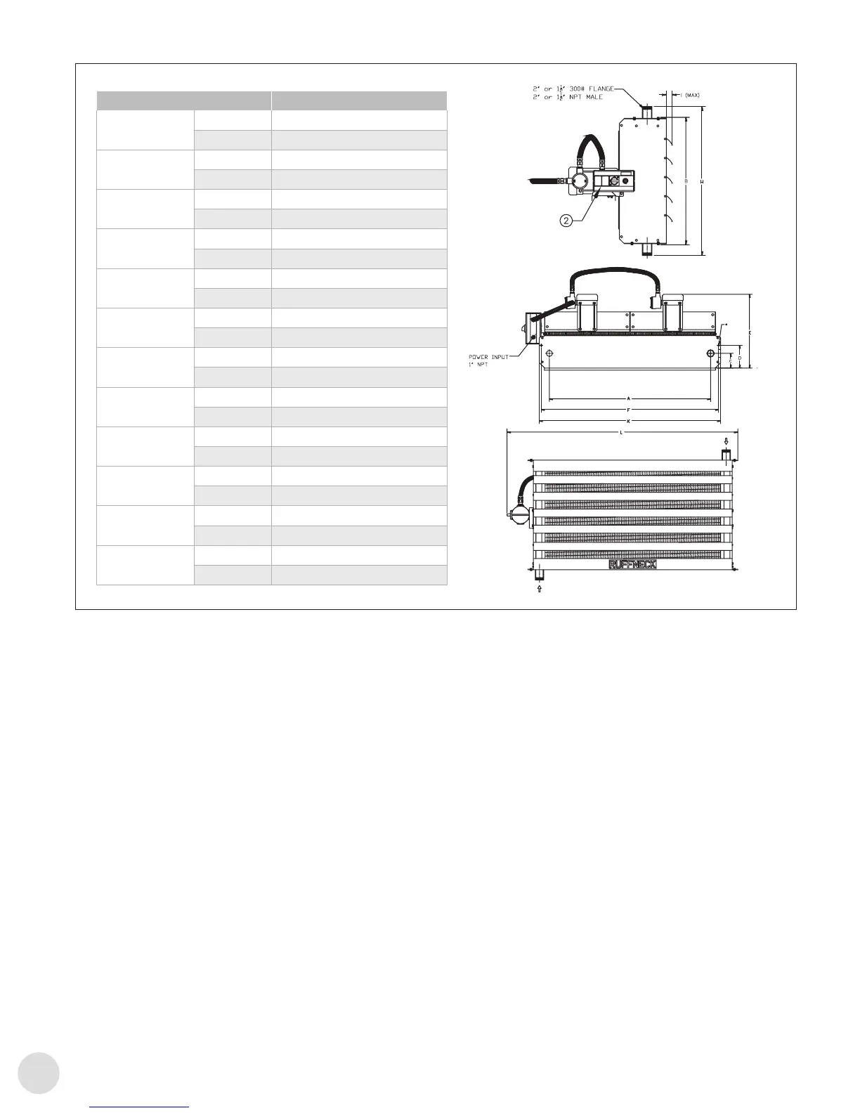
FIGURE 3
FIGURE 2
AH-24B Tandem
A
in. 52-15/16
mm 1345
B
in. 31-1/2
mm 800
C
in. 4-13/16
mm 122
D
in. 7-7/16
mm 189
E
in. 24-3/16
mm 615
F
in. 58-1/4
mm 1480
G
in. 9/16
mm 14.3
H
in. 36-7/8
mm 937
I
in. 2-1/16
mm 53
J
in. 5/8
mm 16
K
in. 59-1/2
mm 1512
DIM AH-12A AH-16A AH-20A AH-24A
A
in 15-13/16 19-13/16 23-13/16 27-7/8
mm 401 503 605 707
B
in 19-7/16 23-1/2 27-1/2 31-1/2
mm 494 596 698 800
C
in 4-3/16 4-3/16 4-3/16 4-3/16
mm 107 107 107 107
D
in 7-15/16 7-9/16 7-3/16 6-7/8
mm 201 192 183 174
E
in 23-5/8 23-5/8 23-5/8 23-5/8
mm 600 600 600 600
F
in 18-3/16 22-3/16 26-3/16 30-3/16
mm 462 564 665 766
G
in 9/16 9/16 9/16 9/16
mm 14.3 14.3 14.3 14.3
H
in 23-7/8 27-7/8 31-7/8 35-7/8
mm 606.5 708.5 809.5 911.5
I
in 1-9/16 1-9/16 1-9/16 1-9/16
mm 39 39 39 39
J
in 5/8 5/8 5/8 5/8
mm 16 16 16 16
K
in 27-1/2 31-5/8 35-1/2 39-5/8
mm 698.5 802.5 903 1005
L
in. 65-1/2
mm 1662.5
Dim. AH-24B Tandem
A
in 52-15/16
mm 1345
B
in 31-1/2
mm 800
C
in 4-13/16
mm 122
D
in 7-7/16
mm 189
E
in 24-3/16
mm 615
F
in 58-1/4
mm 1480
G
in 9/16
mm 14.3
H
in 36-7/8
mm 937
I
in 2-1/16
mm 53
J
in 5/8
mm 16
K
in 59-1/2
mm 1512
L
in 65-1/2
mm 1662.5
Figure3
5. Temperature Control
5.1 If required, the unit heater’s output may be
thermostatically controlled by the following:
– Airow through the heat exchanger can be turned
on and off by thermostatically controlling the fan
motor. Usually the ow of the heat transfer medium is
allowed to pass through the heat exchanger without
interruption. This is the most economical method of
controlling the heater.
– Heat transfer medium ow may be controlled by a
thermostatic valve, while allowing the fan motor to
run continuously to circulate room air.
– Absolute control of the heater output from the heat
exchanger will require that the fan and heat transfer
medium be shut off. Such control of the heater
output is possible by a thermostatic valve control in
combination with the thermostatic fan control.
6. Final Inspection
6.1 Before application of electrical power:
– Check that all connections are secured and
comply with the applicable wiring diagram (see
C.2 Motor Wiring Diagrams, page8) and code
requirements.
– Conrm the power supply is compatible with the
data plate rating on motor.
– Remove any foreign objects from heater.
– Ensure all electrical covers are well secured.
– Ensure the fan rotates freely, ensure air exits through
louvers and the fan rotates counterclockwise when
viewed from the rear of the heater.