Hardware Installation and Reference Guide Product Overview
25
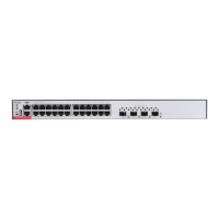
Front Panel
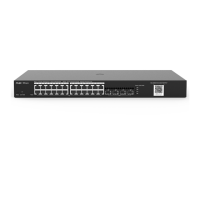
Figure 1-26 Front Panel of RG-S5310-24GT4XS-P-E
2. Management Port LED
3. PWR1 Status LED
4. PWR2 Status LED
5. LED Mode Indicator
6. LED Mode Button
8. Console Port
9. Management Port
10. 10/100/1000Base-T Ethernet Port
11. 10GE SFP+ Port
12. Port LED
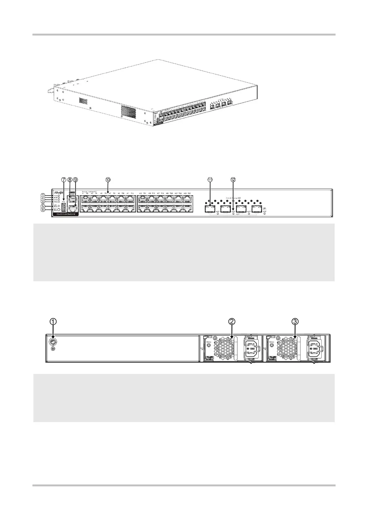
Back Panel
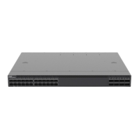
Figure 1-27 Back Panel of RG-S5310-24GT4XS-P-E
1. Grounding Stud
2. Power Supply Module Slot 1 (A filler panel is required if the
slot is vacant.)
3. Power Supply Module Slot 2 (A filler panel is required if the
slot is vacant.)
Power Supply
The RG-S5310-24GT4XS-P-E switch supports dual power supply modules. See Chapter 1.13 for details about the power supply modules.
The switch can be powered on by either one power supply module or dual power supply modules. If both power supply modules are
used, the switch works in the power redundancy mode.
 Loading...