Ruijie RG-ES100 Series Switches Hardware Installation and Reference Guide
3.3.2 Mounting the Switch on the Wall
RG-ES106D-P and RG-ES110D-P can be mounted on the wall. (Mounting screws and wall anchors are customer supplied.)
In actual installation, users need to determine the size and depth of the two mounting holes on the wall based on the sizes
of wall anchors and screws. Ensure that the wall anchors can be inserted into the holes, only the outer edges of the wall
anchors are left outside the wall, and screws can be tightly fastened to the wall.
The following process takes RG-ES110D-P as an example. The steps of mounting the switch on the wall are as follows:
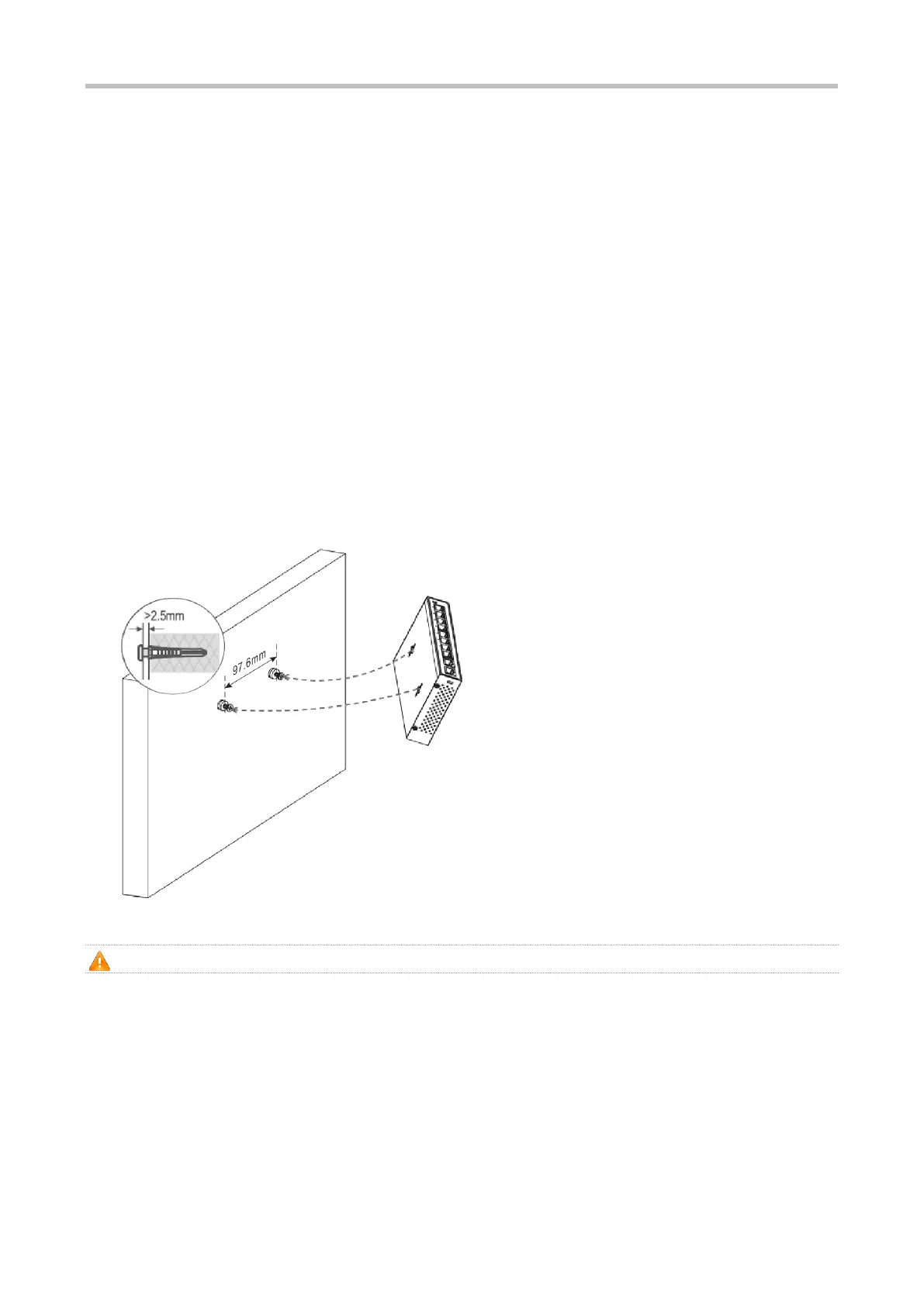
Step 1: As shown in Figure 3-1, drill two holes 97.6 mm (3.84 in.) far away from each other, and the line of connecting the
two holes is horizontal.
Step 2: Insert wall anchors into the holes and ensure that the outer edges of the wall anchors are aligned with the wall.
Step 3: Put screws (ST4.2x20 recommended) into the wall anchors and ensure that the distance between the inner side
of the screw head and the outer edge of the wall anchors not be smaller than 2.5 mm (0.10 in.) so that the device can be
securely mounted on the screws.
Step 4: Align the two mounting holes on the bottom of the chassis of the device with the screws, and then fasten the device
on the screws.
Figure 3-4 Mounting the Switch on the Wall
Suitable for mounting on concrete or non-combustible surface only.
3.3.3 Mounting the Switch on a Table
The following process takes RG-ES110D-P as an example. Place the switch on a table, as shown in Figure 3-2.
Figure 3-5 Placing the Switch on a Table

 Loading...