Hardware Installation and Reference Guide Product Overview
22
2. PoE status LED
3. PoE button
4. USB port
6. 10/100/1000Base-T adaptive Ethernet port
7. SFP port status LED
8. SFP port
You can press the port LED mode switching button (PoE button) to switch the port status indicator function (port PoE power
supply indicator and port rate indicator). Hold down the button for more than 2 seconds to ensure successful switching.
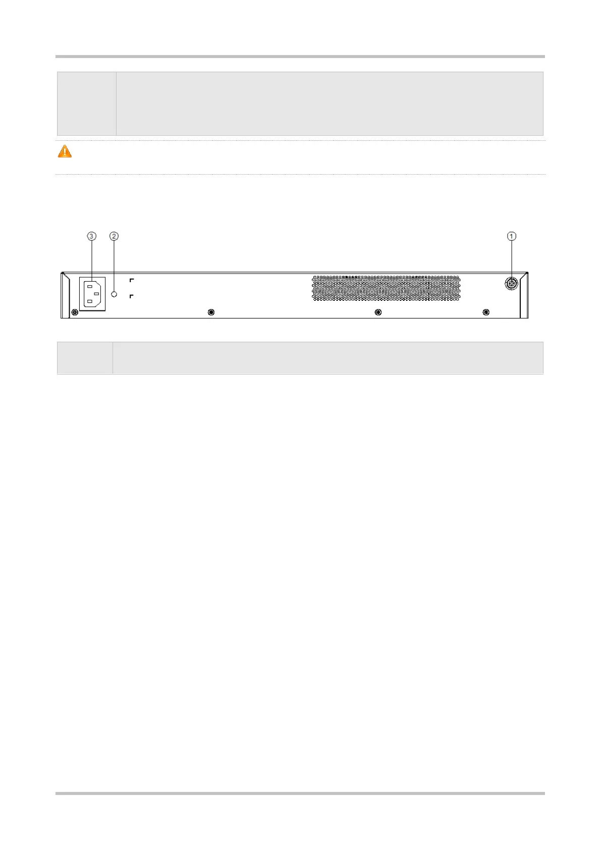
Back Panel
Figure 1-23 Back Panel of RG-S2915-24GT4MS-P-L Switch
2. Power cord retention clip hole
Power Supply
The RG-S2915-24GT4MS-P-L switch adopts an AC power supply.
AC input:
Rated voltage range: 100 V AC to 240 V AC; 50 Hz/60 Hz
Maximum voltage range: 90 V AC to 264 V AC; 47 Hz to 63 Hz
Frequency: 50 Hz/60 Hz
Rated current: 6 A
Power cord requirements: 10 A power cord
Heat Dissipation
The RG-S2915-24GT4MS-P-L switch adopts the left-to-right airflow for heat dissipation to ensure that the device works properly under
specified environment. When placing a chassis, maintain a minimum clearance of 10 cm (3.94 in.) on both sides and around the back
panel of the chassis for air circulation. Dust the device every three months to avoid blocking the ventilation openings on the housing.
Figure 1-24 Airflow Direction of RG-S2915-24GT4MS-P-L Switch

 Loading...