Hardware Installation and Reference Guide Installing the Switch
25
in the Ethernet and fiber-optic cables. The front panel of the switch should be at least 10 mm (0.39 in.) away from
the front door of the cabinet. Please confirm the following before installing the switch:
The cabinet is secured.
The modules in the cabinet are installed.
There are no obstructions in and around the cabinet.
The device is prepared and transported to a location close to the cabinet.
Do not install the optical module before the switch is mounted.
3.4.1 Mounting the Brackets
(1) Take out two L-shaped brackets and 12 M4 x 8 FMO screws from the package.
(2) Attach a bracket to each side of the switch and secure the brackets with six M4 x 8 FMO screws respectively.
Figure 3-1 Mounting the Brackets
3.4.2 Mounting the Switch in a Rack
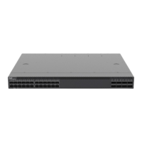
All models of the RG-S6150-X series switches can be installed in a 19-inch EIA rack. Mount the switch in the
rack with the front panel face forward. You are advised to use a tray to install the switch and secure the tray on
the bracket, or use the rear bracket provided with the switches.
Figure 3-2 Mounting the Switch in a Rack (Example: RG-S6150-48VS8CQ-X)
Mount the switch on a 19-inch EIA rack.
 Loading...
