Hardware Installation and Reference Guide Installing the Switch
26
Note
The mounting brackets are located at the four of the six screw holes at both sides on the back panel of the
switch.
Distinguish the left and the right rear brackets according to the marked directions.
The rear brackets provided are only applicable for cabinets with depth of 800 mm (31.50 in.) to 1200 mm
(47.24 in.).
3.4.3 Mounting the Switch on a Workbench
In some cases, users do not have a 19-inch EIA rack. The common solution is to place the switch on a clean
workbench. The operation is simple as follows:
(1) Attach the four rubber pads to the four corners on the switch bottom.
(2) Place the switch on the workbench and ensure good ventilation condition around the switch.
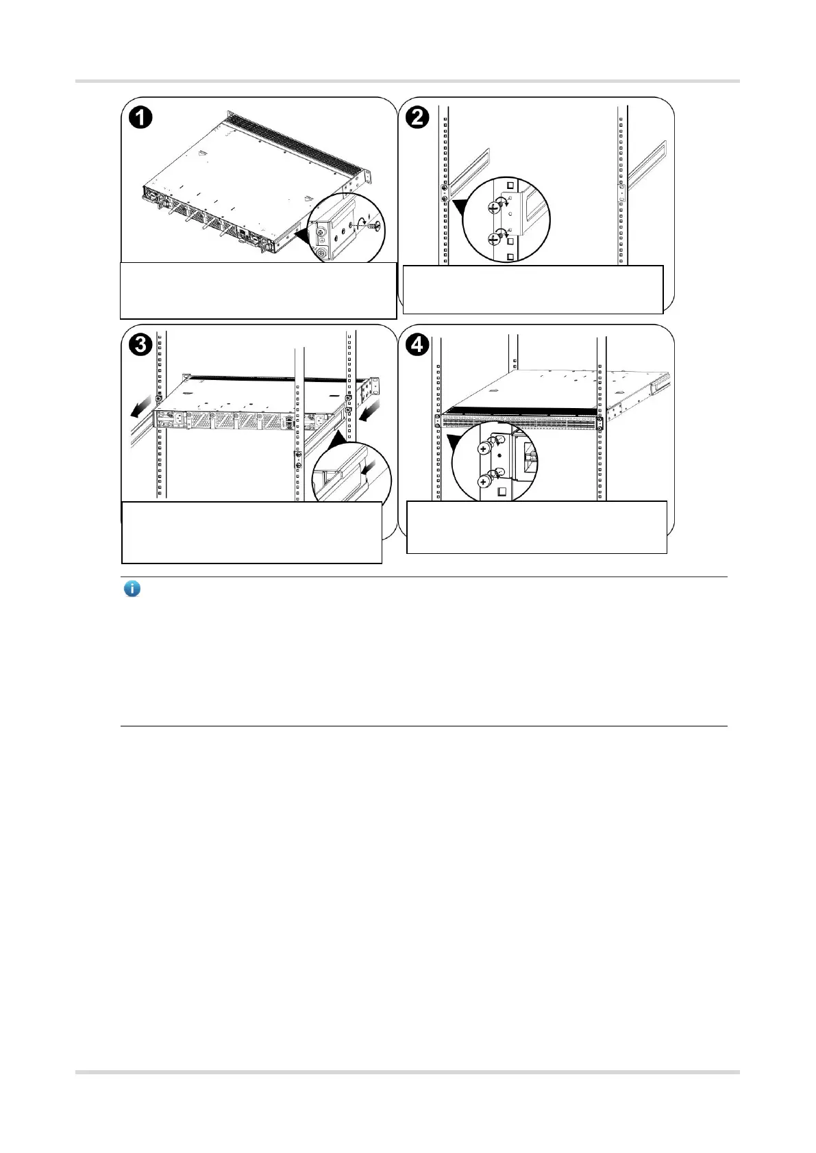
Use the provided screws to attach a rack-
mount guide to each side of the switch.
Attach the left and right guide rails to the
rack.
Slide the rack-mount guides onto the guide
rails, and then gently slide the switch all the
way into the rack.
Tighten the screws to secure the brackets
on the rack.
 Loading...


