EasyManua.ls Logo

Runxin 63510 User Manual

Runxin 63510
49 pages
To Next Page IconTo Next Page
Page #1 background image
Multi-functional Flow Control Valve for
Water Treatment Systems
63510Old ModelN74A1
63610Old ModelN74A3
63510BOld ModelN74B1
63610BOld ModelN74B3
Instruction Manual
Please read this manual in details before using the valve
and keep it properly in order to consult in the future.
0WRX.466.510
International Patent No.WO 2006/007772
China Patent No.ZL02220153.X
ZL200420078956.5
US Patent No.7549446
India Patent No.232582
Russia Patent No.2349819
South Korea Patent No.10-0914137
Mexico Patent No.268581
Australia Patent No.2005263257
Philippine Patent No.1-2006-502553
Taiwan Patent No.M287896

Table of Contents

Question and Answer IconNeed help?

Do you have a question about the Runxin 63510 and is the answer not in the manual?

Runxin 63510 Specifications

General IconGeneral
BrandRunxin
Model63510
CategoryControl Unit
LanguageEnglish

Summary

Multi-functional Flow Control Valve

Instruction Manual Overview

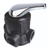
Provides an overview of the instruction manual for the flow control valve.

Softener System Configuration

Parameter Settings

Details the parameters for configuring the softener system.

Important Notices

Safety and Operation Guidelines

Key guidelines for safe and proper operation and installation of the valve.

Product Overview

Applications and Characteristics

Describes the valve's applications, features, and installation methods.

Meter Type Selection and Interlock Function

Control Outputs and Inputs

Service Conditions

Operating Environment and Water Quality

Specifies required working conditions and inlet water quality standards.

Product Dimensions and Structure

Structure Charts for Valve Models

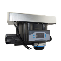
Illustrates the structural components of different valve models.

Technical Parameters and Installation

Installation Guide and Notices

Provides installation guidance, notices, and advice on device location.

Pipeline Installation Steps

Flow Meter and Pipeline Connections

Drain and Brine Line Connections

Basic Setting and Usage

PC Board Functions and Controls

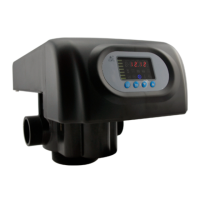
Explains PC board functions, indicators, and button lock features.

Control Button Operations

Parameter Specifications

Parameter Settings Overview

Covers time of day, control modes, and service day/hour settings.

Detailed Parameter Settings

Process Display

Display Status Illustrations

Illustrates the various figures shown on the display during different operational stages.

Valve Usage Guidelines

Operational Procedures and Adjustments

Covers brine tank maintenance, water testing, and capacity adjustments.

Applications

Softener Flow Charts

Diagrams showing water flow during service, rinse, and refill cycles.

Flow Chart Status Details

PC Board Functions and Connections

Control Board Connector Functions

Details the functions and applications of main control board connectors.

Signal Output and Wiring

Inlet Valve Wiring and Interlock

Liquid Level Control for Inlet Pump

Booster Pump and System Interlock

Pressure Relief and Remote Control

System Configurations

Interlock and Series System Wiring

Illustrates wiring for interlock and series systems with multiple valves.

System Configuration and Flow Rate

Configuration, Flow Rate, and Injector Data

Covers product configurations, flow rate curves, and injector parameters.

Injector and DLFC Configuration

Parameter Settlement Calculations

Regeneration Cycle Time Calculations

Formulas for calculating service, backwash, rinse, and refill times.

Exchange Factor, Regeneration Time, and Enquiry

Parameter Setting Procedures

Setting Time, Mode, and Regeneration Time

Step-by-step guide for setting key operational parameters.

Setting Water Capacity, Resin, and Hardness

Setting Rinse and Refill Times

Setting Regeneration Intervals and Signal Output

Trial Running the Valve

Trial Running Procedure

Step-by-step guide for conducting the initial trial run of the installed valve.

Troubleshooting Guide

Control Valve Faults

Common problems and solutions related to control valve malfunctions.

Brine Draw and Salt Usage Issues

Water Flow and Regeneration Issues

Brine, Water, and Capacity Issues

Controller Faults and Error Codes

Controller Display and Error Troubleshooting

Guides for troubleshooting controller display issues and specific error codes (E1-E4).

Assembly and Parts Identification

Valve Body Assembly Diagram

Exploded view illustrating the assembly of the valve body.

Component Part Numbers (N74A3/N74A1)

Flow Meter and Side Connector Details

N74B3 Structure Chart

Spare Parts for N74B3/N74B1

Warranty Information

Warranty Conditions and Claims

Outlines the terms and conditions for warranty coverage and service.

Related product manuals