MODEL: N74A1-63510/N74A3-63610/N74B1-63510B/N74B3-63610B
20
To ensure not only
one control valve
regeneration or
washing in system.
Use in RO Pre-treatment, water
supply together but regeneration in
turn. Second grade ion exchange
equipment, etc.
Remote
handling
connector
Receipt signal to
make the control
rotate to next circle
It is used for on-line inspection
system, PC connection, and realize
automatically or remote controlling
valve.
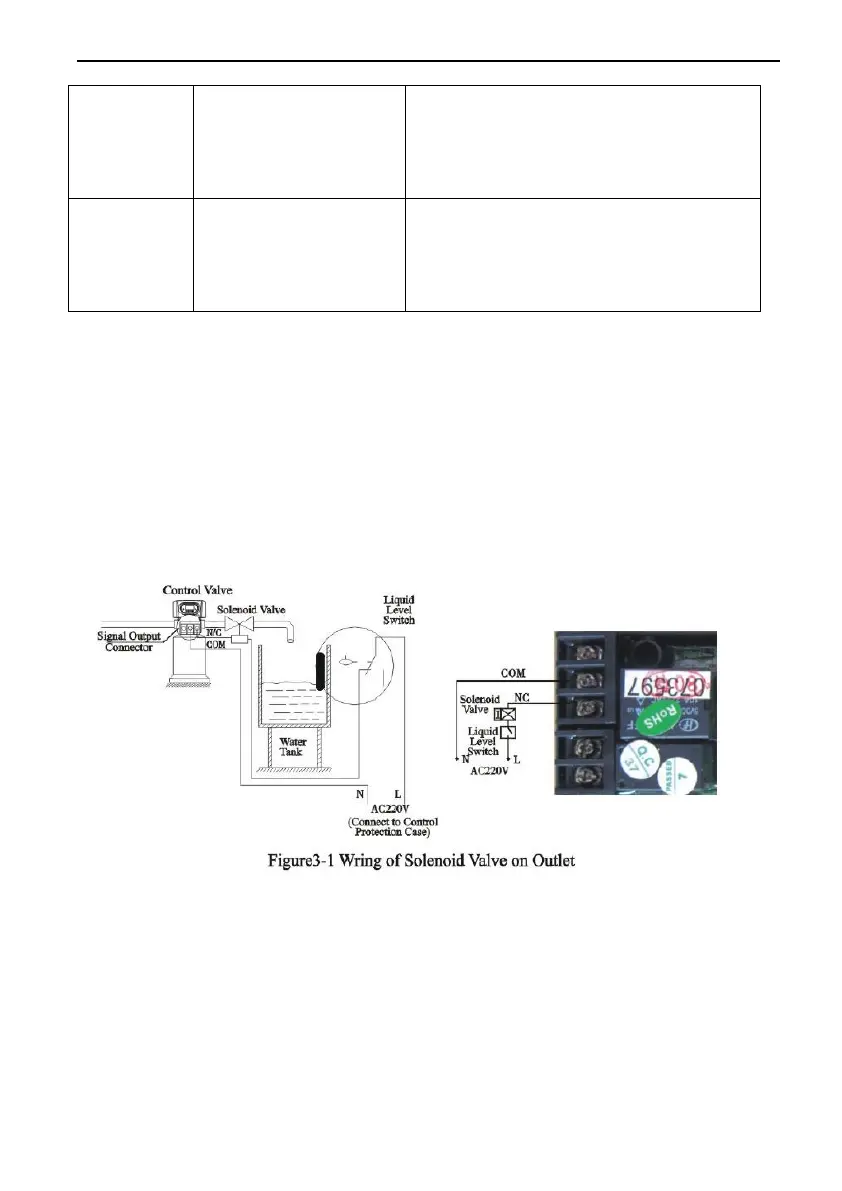
A. Signal Output Connector
1) Control Solenoid Valve (Set b-01)
① Solenoid valve on outlet controls water level in brine tank.
Instruction: If system strictly require no hard water flow from outlet in
regeneration cycle( Mainly for no hard water flow out when valve is
switching or valve in backwash or brine drawing positions), a solenoid
valve could be installed on outlet, the wiring refer to Figure 3-1:
Function:
When valve in service status, if soft water tank is short of water,
solenoid valve is open to supply soft water, but if water tank has enough
water, solenoid valve is closed, so no soft water supplied.
When the valve in backwash status, there is no signal output. So,
solenoid valve is closed, and now water flow into soft water tank.
② Solenoid Valve on Inlet( Set b-02)
Instruction: When inlet pressure exceeds 0.6 MPa, install a solenoid valve