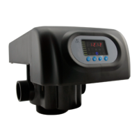
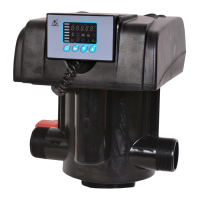
MODEL: N74A1-63510/N74A3-63610/N74B1-63510B/N74B3-63610B
27
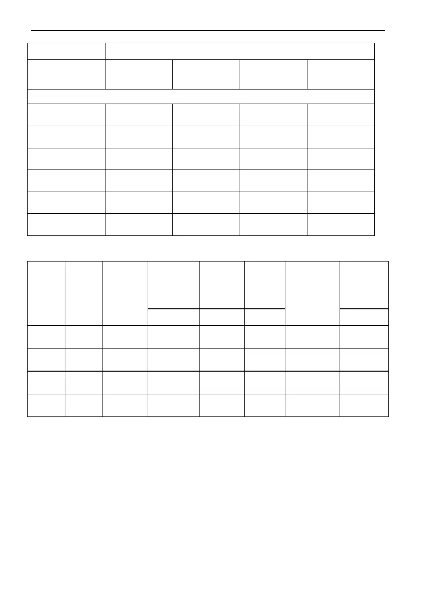
3)Configuration for Standard Injector and Drain Line Flow Control
Remark: Above data for the product configuration and relevant
characteristics are only for reference. When put in practice, please subject
to the different requirements of raw water hardness and application.