MODEL: N74A1-63510/N74A3-63610/N74B1-63510B/N74B3-63610B
9
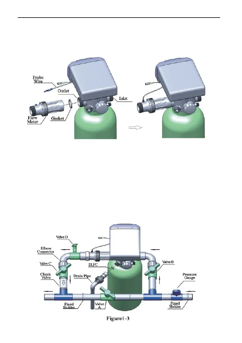
② Install flow meter
As Figure1-2 shows, put the sealing ring into nut of flow meter, screw in
water outlet; insert the sensor into flow meter.
Figure 1-2
③ Pipeline connection
a. Install a pressure gauge in water inlet as figure 1-3.
b. Install valve A, B, C, D in inlet, outlet, inlet pipeline and outlet pipeline.
Valve D is sampling valve.
c. Install a check valve on outlet pipe.
d. Inlet pipeline should be in parallel with outlet pipeline. Support inlet and
outlet pipeline with fixed holder.