MODEL: N74A1-63510/N74A3-63610/N74B1-63510B/N74B3-63610B
10
Note:
●If the water outlet or water tank is installed higher than control valve
or parallel interlock system with multi-outlets, a liquid level controller
must be installed in brine tank. Or else, the water in water outlet or
water tank will flow backwards into brine tank when backwash.
●If making a soldered copper installation do all sweat soldering
before connecting pipes to the valve. Torch heat will damage plastic
parts.
●When turning threaded pipe fittings onto plastic fitting, use care not
to cross thread or broken valve.
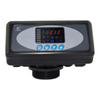
●If the valve belongs to time clock
type ( N74A1 or N74B1), there are no
step ②.
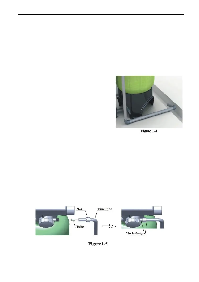
④ Install drain pipeline
Insert drain line flow control into drain
outlet, use UPVC glue to connect drain
outlet with UPVC drain pipeline as
Figure 1-4 shows.
Note:
●Control valve should be higher than
drain outlet, and be better not far from the drain hose.
●Be sure not connect drain with sewer, and leave a certain space
between them, avoid wastewater be absorbing to the water treatment
equipment, such as showed in the Figure1-4.
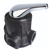
⑤ Connect brine tube
a. As Figure1-5 shows, slide 1/2″ brine tube hose connector over end of
brine tube.
b. Insert tube bushing into the end of brine tube.
c. Tighten brine draw hose connector onto brine line connector.
d. Connect the other end of brine tube with the brine tank. (The liquid
level controller and air-blocker should be installed in the brine tank.)
Remark: The brine tube and drain pipeline should not be bended or
plugged.